The distance between the gauge gauge and LB2 must be large enough to allow the gauge sufficient
time to generate valid speed measurements before the object reaches LB2 and triggers length
measurement. Distance “L” between LB1 and LBβ must also be less than the minimum object length.
IMPLEMENTATION
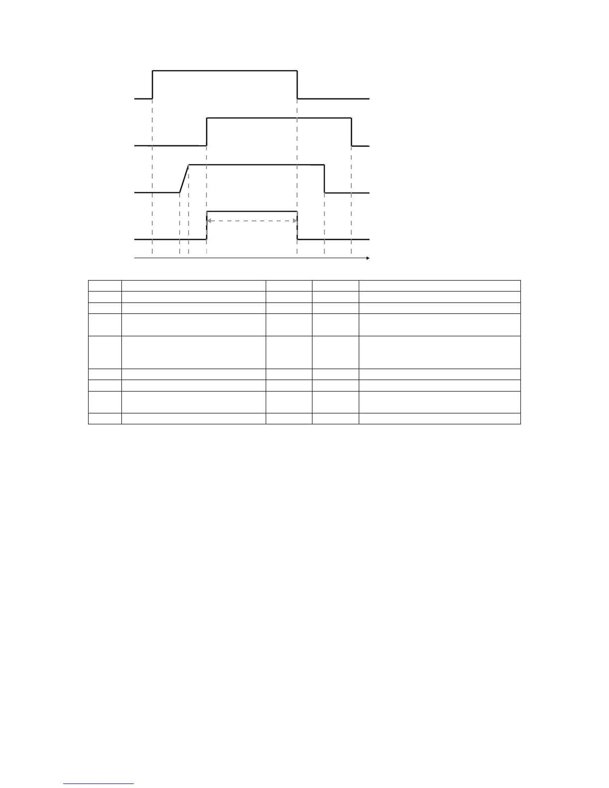
Light barriers LB1 and LB2 can be connected to any 2 of the 3 logic inputs provided on the gauge.
The behaviour of the gauge can be configured to trigger length measurement only when both LB1
and LB2 are blocked.
Both logic inputs should be configured to “Length hold” mode. An active logic input in “Length hold”
mode will cause the gauge to freeze length readings and force the displayed speed to zero (however,
internally the gauge will continue to accurately measure speed if an object is present). Hence each
logic input should be configured to be active when its corresponding light barrier is clear.
A “Length offset” corresponding to the distance “L” between the two light barriers can also be
programmed in to gauge. The gauge will then automatically add this “Length offset” to its length
measurement display and output.
The length measurement generated by the gauge will be ready to read by other production control
equipment when the output of LB1 transitions from blocked-to-clear (the object’s trailing edge passes
through LB1). A momentary pulse may be sent to the third logic input on the gauge to reset the length
measurement once it has been read out by other production control equipment.
 Loading...