EasyManuals Logo

Proton SL mini 3060 User Manual

Default Icon
127 pages
To Next Page IconTo Next Page
To Previous Page IconTo Previous Page
Page #32 background imageLoading...
Page #32 background image
Page 32 of 126
Proton Products SL mini and SLR mini Series Speed and Length Gauges Instruction Manual - issue 1s
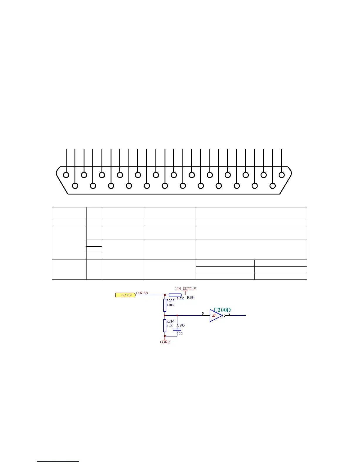
LASER ENABLE
The laser enable input is provided for compliance with laser safety regulations.
The laser diode in the gauge may be energised only if the “LSR_ENpin (pin 14) is connected
(via an external user-supplied switch contact) to any one of the “DGND” pins (pins 2, 15, 24).
The gauge requires a few minutes for the laser temperature to stabilise and for valid
measurement after “LSR_EN” is connected to “DGND”. For this reason, it is recommended
that the laser enable input is connected to a safety interlock that is active infrequently, such
as a maintenance lock-out key switch.
Safety interlocks that are frequently activated and require the gauge to immediately resume
measurement upon deactivation (such as a machine guard door) should be connected to the
shutter enable input (“SHUT_EN”) described in the next section.
Connector type: DB25 female (socket)
Functional
group
Pin
Designation
Description
Notes
Shield
S
Shield
Shield
Connect to cable and plug shields
Power
supply and
ground
25
+24V SUPPLY
+24V power
supply
2
DGND
Power supply and
signal ground
(0V)
15
24
Laser
enable
14
LSR_EN
Laser enable
Connection
Laser diode state
Open
Off (no emission)
Connected to DGND
On (emission)
1
14
2
15
3
16
4
17
5
18
6
19
7
20
8
21
9
22
10
23
11
24
12
25
13

Table of Contents

Questions and Answers:

Question and Answer IconNeed help?

Do you have a question about the Proton SL mini 3060 and is the answer not in the manual?

Proton SL mini 3060 Specifications

General IconGeneral
BrandProton
ModelSL mini 3060
CategorySecurity Sensors
LanguageEnglish

Related product manuals