DFM 6.1 INSTRUCTION MANUAL
32
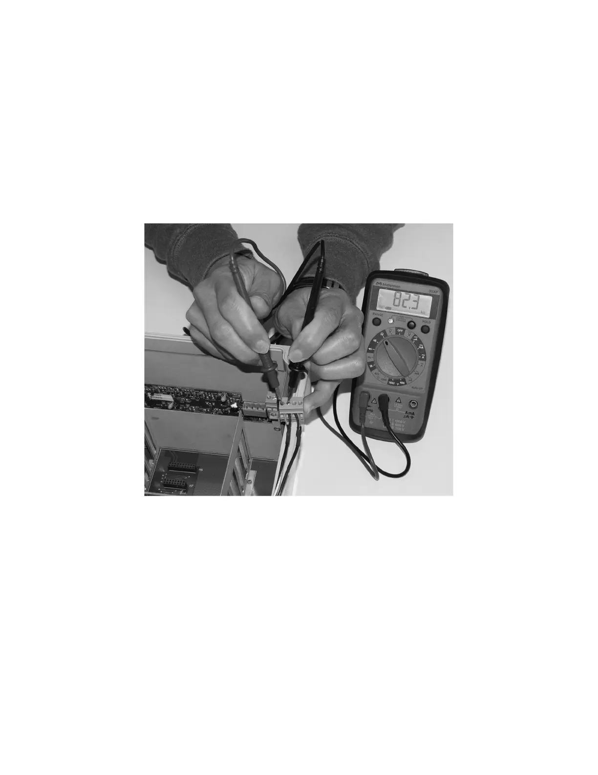
SENSOR CABLE RESISTANCE TEST
Unplug the green sensor terminal from the Doppler board and connect the sensor wires as shown. With a
multimeter, perform resistance checks for each set of wires. One single loose terminal may cause false readings.
Test across shield and core of each wire: TMTR (black/white) and RCVR (black). Resistance should be around 82.5K
ohms for any cable length. High readings indicate an open circuit and low readings indicate a short or partial short
in the sensor cable.
 Loading...