Page 55
The 18-24 vdc (power) supply should be connected to the red cable coming from
the transducer.
The 5-7 vdc (signal) should be connected to the white cable coming from the
transducer.
The 0 vdc supply should be connected to the Black & Green cables coming from
the transducer.
The transducer will not operate correctly below 18vdc so on long cable runs the
extension cable should be of a sufficient size/quality to ensure this is the case.
Establishing the correct echo.
If we are certain the unit is operational and working correctly, but not reading the
right level or distance then we need to follow the P21 procedure as listed below in
order to obtain the correct reading.
The unit has unique DATEM (Digital Adaptive Tracking of Echo Movement)
software that can cover false echoes whilst maintaining a fix on the true echo.
The software will then adapt to any changes to the echo profile in front of the
moving target enabling Pulsar to keep the correct reading under constantly
changing process conditions.
In order to initially cover all the false echoes we need to get the level in the
application to its lowest measuring point and then tell the control unit where the
true echo is, it will then mask out all the false echoes in between the transducer
and the target giving us a correct reading
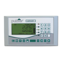
P21 - Follow the Steps Below.
Before starting this procedure you will need to establish the distance between the
face of the transducer and the measured surface to within approx 10cm.
Key in the passcode 1997 (four dashes will appear in the display) and press
enter.
Display will show ‘wait’ then after a few seconds ‘Quick Set-up’.
Key in 21 and press enter.
Display shows 0.000 & Set Dist 1. Or ( Sel Peak) on some older units.
Key in the distance from the transducer face to the product (within 20cm)
and press enter.
Display shows ‘Capturing’ then after a few seconds ‘Enter If Sure’ press
enter.
 Loading...

