EasyManua.ls Logo

Pyronix ENFORCER Series User Manual

Pyronix ENFORCER Series
44 pages
To Next Page IconTo Next Page
To Previous Page IconTo Previous Page
Page #14 background imageLoading...
Page #14 background image
Enforcer: Programming Manual
Page: 14
Set Point Sets
A “Set Point” means that you can program the keypad / reader to set certain Areas only.
This is used in conjunction with the Areas allocated to a user code.
For example, if a user code is programmed to operate Areas ‘A’ and ‘B’, but the keypad /
reader is only programmed to Set Area ‘A’, then the system will arm only Area ‘A’
Selects the area that the device will be defaulted to.
Set Point Unsets
An “Unset Point” means that you can program the keypad / reader to Unset certain
Areas only. This is used in conjunction with the Areas allocated to a user code.
For example, if a user code is programmed to operate Areas ‘A’ and ‘B’, but the keypad /
reader is only programmed to Unset Area ‘A’, then the system will Unset only Area ‘A’.
Set Point In
The keypad needs to also be told which Areas it is operating “in”. For example, a keypad may
only be needed to operate in Area A, but other code users may use the keypad to quick set
other Areas (such as a cleaner, director, caretaker etc). Therefore if Areas A and B are
selected in the previous options (Arm point sets and unset), but Area A only is selected in
‘Set point in’, then Area B will quick arm once a valid tag/code has been entered. To
program Areas operating with their programmed timer, then the Areas need to be
entered into the “Set Point In” function.
Set Point Description
A name and location can be entered here. The name will appear on the display if an alarm has
occurred, the location is used for a more detailed reference if required. E.g. Name = Entrance
Keypad. Location = Hall
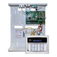
Programming Keypads: Assign Keypads/Readers
1. Press or to scroll to 'ASSIGN KEYPADS/READERS'.
Press .
2. Press [ or ] to select the address. Press .
3. 'Type' will be displayed. Press 0 to select keypad.Press
4. 'Set Point Sets' will be displayed. Select the area(s). Press .
Set Point Unsets' will be displayed. Select the area(s). Press
. 'Set Point In' will be displayed. Select the area(s). Press
.
5. 'Set Point Description' will be displayed. Press to enter the
name and location if required.
6. 'Enter Name' will be displayed. Enter the name of the keypad
and press .
7. 'Enter Location' will be displayed. Enter the location of the
keypad and press .
8. Press [ or ] to select another device address to program
(0-3) or press the key to return to the Engineer menu
Programming Readers for Set Point or Unset Only: Assign
Keypads/Readers
1. Press or to scroll to 'ASSIGN KEYPADS/READERS'.
Press .
2. Press [ or ] to select the address. Press .
3. 'Type' will be displayed. Press 1 to select reader.Press
4. 'Reader is' will be displayed. Press 0 for 'Set Point' or press
1 for 'Unset Only' Press .
5. 'Set Point Sets' will be displayed. Select the area(s). Press .
ASSIGN KEYPADS/
READERS?
Address
[0]
Type
Keypad [0]
Set Point Sets
Set Point
Description?
Enter Location
_
ASSIGN KEYPADS/
READERS?
Address
[1]
Question and Answer IconNeed help?

Do you have a question about the Pyronix ENFORCER Series and is the answer not in the manual?

Pyronix ENFORCER Series Specifications

General IconGeneral
Frequency868MHz
Operating Temperature-10°C to +40°C
User CodesUp to 50
Battery BackupYes, rechargeable battery
Remote ControlYes, via smartphone app and keyfob
UsersUp to 50
Mobile AppYes
Event LogYes, stores events
Siren OutputYes, built-in and external options
CompatibilityCompatible with Pyronix peripherals

Summary

1. The Engineer Menu

1.1 Accessing The Engineer Menu

Procedure to enter the Engineer Menu using the default code.

1.2 Exiting The Engineer Menu

Steps to exit the Engineer Menu.

1.3 Useful Engineer Menu's

Overview of key functions within the Engineer Menu.

2. General Information

2.1 Default Codes

Lists default user, manager, and engineer codes.

2.2 Initial Power Up

Steps to follow during the first power-up of the system.

2.3 Testing The Keypad

Procedure to test all keypad LEDs and the LCD screen.

2.5 Text Programming

How to program text for input names and messages.

2.6 Engineer Function: Set System

How to set and unset the system using the engineer code.

2.7 Engineer Function: Forced Arm On Inputs

Enables setting inputs for testing purposes.

3. The Engineer Menu

3.1 Set Date & Time

Setting the system's date and time.

3.2 Wireless Device Control

Learning and deleting wireless inputs, bells, and arming stations.

3.3 Change Inputs

Programming input types, attributes, areas, and names.

3.4 Choose Mode

Configuring EOL range, EOL mode, and input response time.

3.5 Install ZEMS

Adding Zone Expander Modules (ZEMs) to the system.

3.6 Change Outputs

Programming output types, endstation, ZEM, wireless bell, and module outputs.

3.7 Assign Keypads/Readers

Addressing and configuring keypads and readers.

3.8 Change Timers

Configuring various system timers like entry, exit, and siren times.

3.9 Codes And Users

Managing engineer, master manager, duress, and guard codes.

3.10 Volume Control

Adjusting volume levels for different system sounds.

3.11 System Options

Tailoring system operation with various site-specific settings.

3.11.2 System Displays

Programming text display on the keypad for system status.

3.11.3 Exit Modes

Configuring how the system enters the set state.

3.12 Review Logs

Viewing panel and access logs for system events.

3.13 Engineer Tests

Testing inputs, outputs, batteries, and siren.

3.14 Diagnostics

Performing diagnostics on wired and wireless components.

3.15 Engineer Reset Options

Resetting the system after alarms or faults using engineer codes.

3.16 Alarm Response

Configuring how the system responds to different alarm events.

3.17 Set Up Downloading

Configuring remote or direct PC programming.

3.18 Software Revision

Displaying current software and hub revisions.

3.19 Clean Start

Performing a factory default reset of the system.

Appendix A. Defaults

Appendix B. Input Types

Appendix C. Timers

Appendix D. Output Types

Appendix E. Fault Codes

Related product manuals