14 Network Switch Installation Guide
QuantaMesh T1000 Series
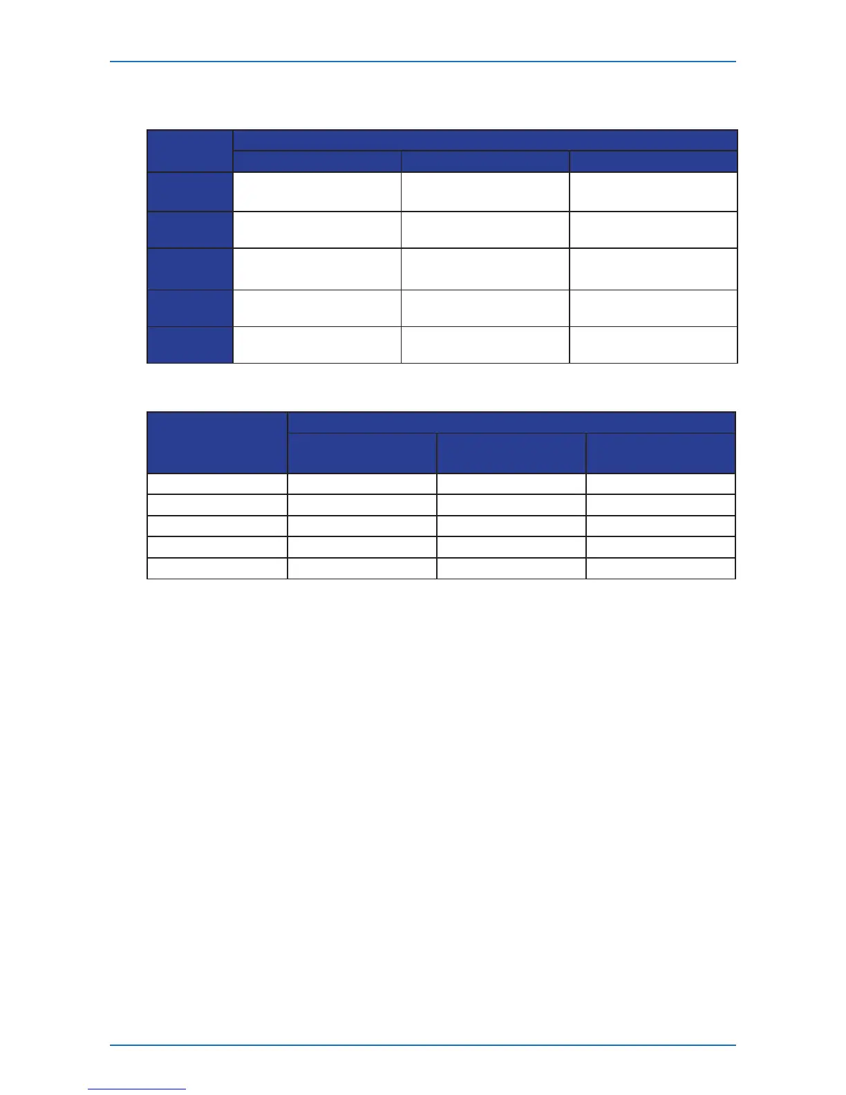
LED Indicators of T1048-P02 Series
• System
System LED
Component
Power System Info OOB
Green Powering On Booting OK
100M
(left LED)
Amber - Booting On Going
1G
(left LED)
Amber
Blinking
- Equipment Error -
Dark Powering O Booting Failed
10M
(left LED)
Blinking - -
Activity
(right LED)
• Data Port
Port Speed
Port Type
RJ-45
SFP
(P02 only)
SFP+
(P02S only)
10M Dark - -
100M Green Dark -
1000M Amber Green Dark
10G - - Green
Blinking Activity (right LED) Activity Activity
Ports of T1048-P02 Series
The switch chassis is equipped with the following ports:
• 48 10/100/1000Base-T
• 4 GE Base-X SFP (T1048-P02) or 4 10GE Base-X SFP+ (T1048-P02S)
• 1 Management ports
• 1 Console port
The chassis has 48 triple speed (10/100/1000) Base-T and 4 SFP/SFP+ ports. Each of these SFP/
SFP+ ports uses an optical transceiver, active optical cables, or direct-attached cable to connect
the SFP/SFP+ port to the servers (downlink connections). For more information on obtaining the
appropriate SFP/SFP+ modules, refer to “Supported Cables and Transceivers” on page 15.
One management port enables you to manage the switch operation using an RJ-45 Ethernet
cable.
One console port enables you to perform the initial conguration by connecting to a PC with the
RJ-45 to DB-9 serial adapter cable.