Network Switch lnstallation Guide 45
Hardware Installation
LED Descriptions
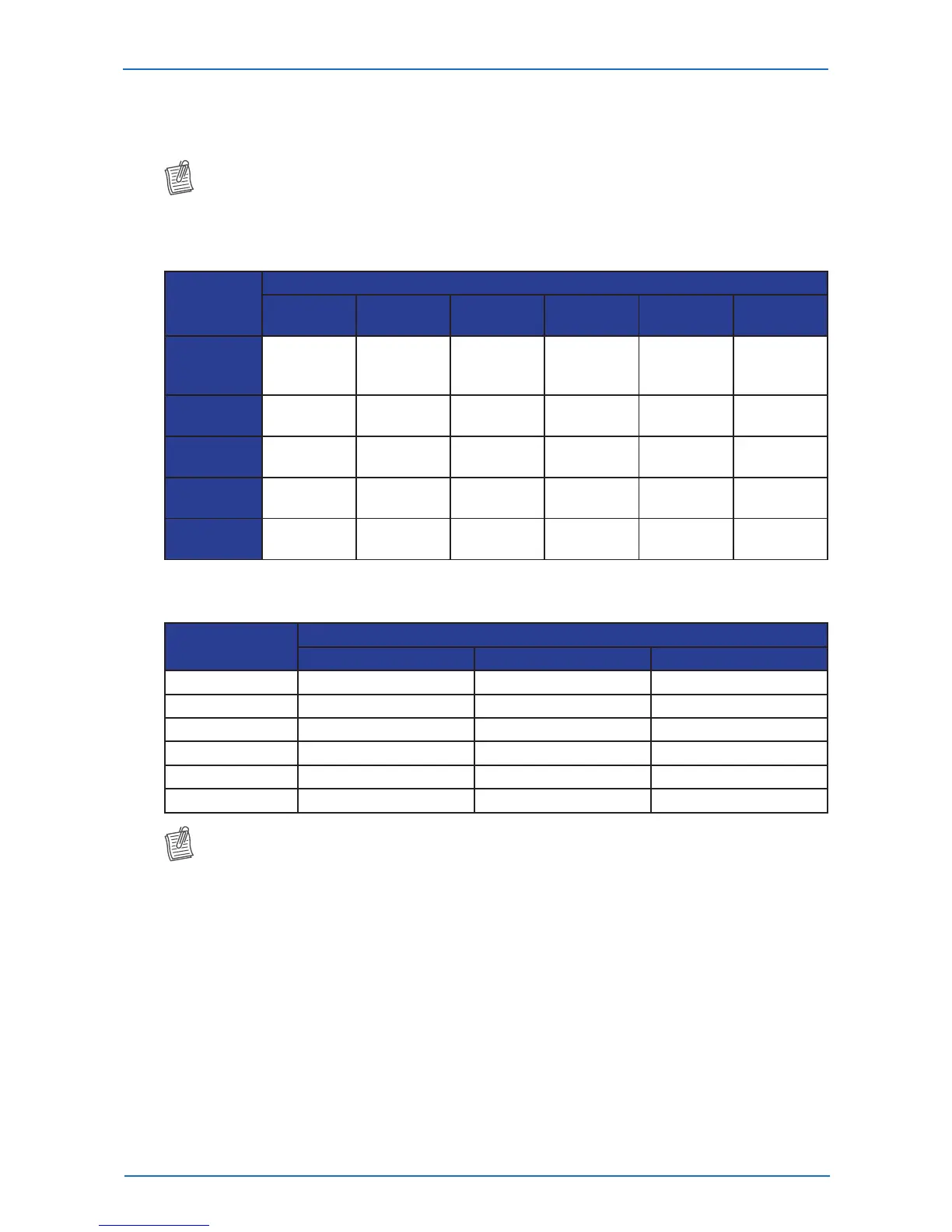
The below table describes the chassis and port LEDs for the QuantaMesh Series switches.
NOTE:
• InformationbelowisnotapplicableforT1048-P02Seriesmodels.
Chassis Indicators
System LED
Component
Power
System
Info
OOB PSU1/2 FAN
FAN1, 2,
or 3
Green
Powering
On
Booting OK
100M
(left LED)
Powering
On
All Fans
Working
Good
-
Amber -
Booting On
Going
1G
(left LED)
- - -
Red - - -
Powering
Failed
Some Fans
Failed
Fan Failed
Dark
Powering
O
Booting
Failed
10M
(left LED)
- - -
Blinking - -
Activity
(right LED)
- - -
Port Indicators
Port Speed
Port Type
RJ-45 SFP+ QSFP+
100M AmberOn - -
1G AmberOn GreenOn GreenOn
10G GreenOn GreenOn GreenOn
40G - - BlueOn
40G (rear panel) - - GreenOn
Activity - Blinking Blinking
NOTE:
• TheLEDlightsuptoindicateavalidlinkhasbeenestablishedbetweentheport.
• TheLEDblinkstoindicatetheportistransmittingorreceivingdata.