40 Network Switch Installation Guide
Hardware Installation
Positioning the Switch
NOTE:
• InformationbelowisnotapplicableforT1048-P02Seriesmodels.
The switch is equipped with Power Supply Units (PSU) and hot-swappable fan modules. It is
important to determine the airow direction of the power supply and fan modules before
installing the switch.
Each fan module handle/plug retainer is color-coded to indicate its airow direction.
• Red: indicates front-to-back airow (air inlet module). See “Front-to-Back Airow” on page
22.
• Blue: indicates back-to-front airow (air outlet module). See “Back-to-Front Airow” on page
22.
To ensure proper airow, make sure that when you install the switch its air intake is positioned in
a cold aisle and the air exhaust is positioned in a hot aisle for your data center.
NOTE:
• Verifythateachmodulehasthesameairowdirection.Makesuretheswitchrunswithallofits
powersupplyandfantraymodulestakinginairfromacoldaisleandexhaustingairtothehot
aisle.
Rack Mounting the Switch
You can install the switch in most standard 19-inch (48.3-cm) racks.
• Due to the switch’s weight, it should be installed by at least two people.
CAUTION
Items Required for Installation
The following items are required to install the switch onto the rack:
√ Phillips screwdriver
√ Screws that t the equipment rack
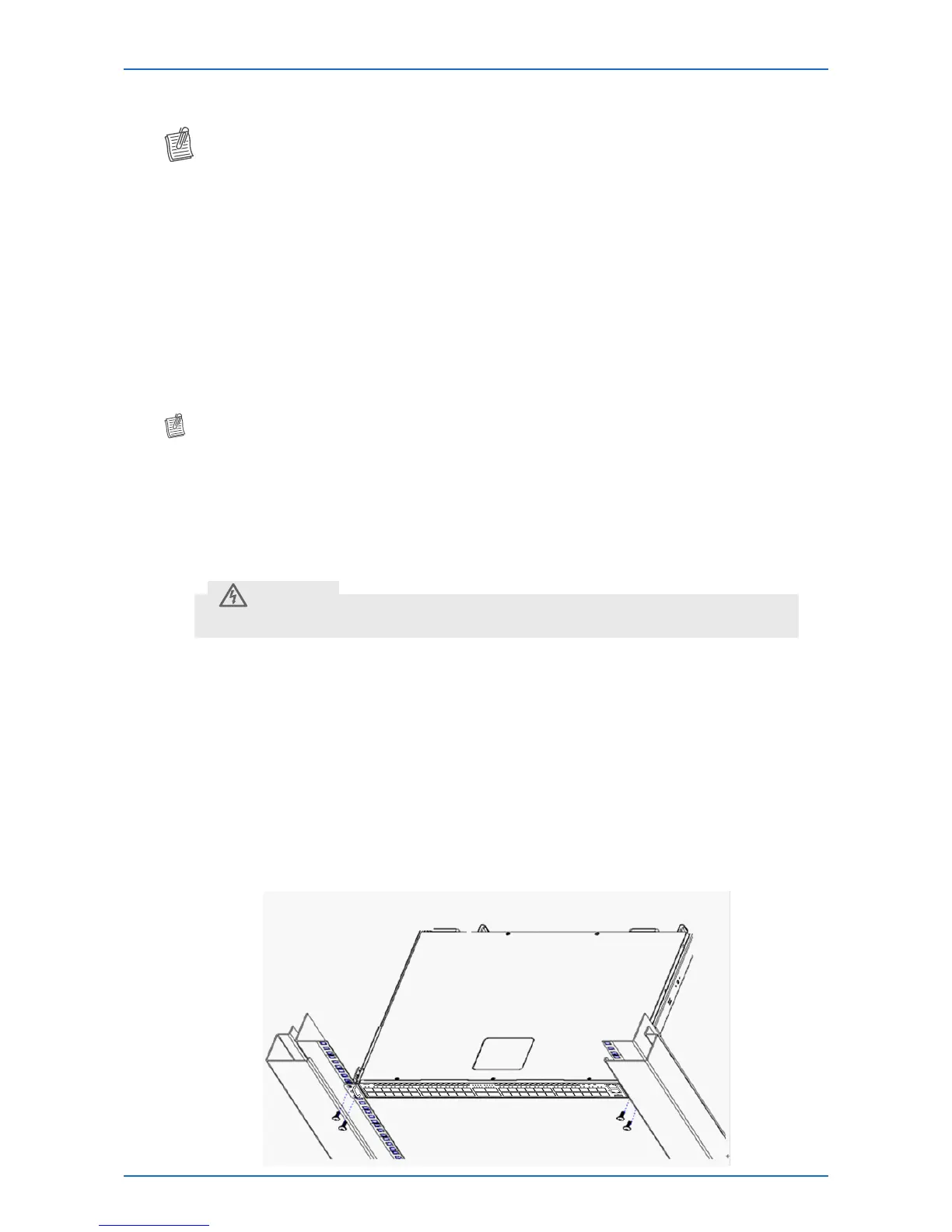
Installing the Switch onto the Rack
The switch can be installed directly onto the rack without the use of the rail.
1 Align the built-in mounting ear to the rack holes.
2 Tighten the screws to secure the switch.
1 2 11 129 107 85 63 4
2
1
4
3
6
5
8
7
10
9
12
11
13 14 23 2421 2219 2017 1815 16
14
13
16
15
18
17
20
19
22
21
24
23
25 26 35 3633 3431 3229 3027 28
26
25
28
27
30
29
32
31
34
33
36
35
37 38 47 4845 4643 4441 4239 40
38
37
40
39
42
41
44
43
46
45
48
47
50/57 605958 52/65 686766
49/53 565554 51/61 646362
PSU1 FAN PSU2
T3048-LY8