Part Replacement Replacing the Inverter Board
CubiScan 125 Service Manual 38
•To remove the gate DB9 and gate DB25 cables, use
the Phillips screwdriver to loosen the screws, and
pull the cables straight out.
•To remove the gate power, proximity sensor, and
encoder cables; unscrew the cables and pull them
straight out.
•To remove the ultrasound sensor cables, press the
tab and pull the cable straight out.
4. Disconnect the ground cable by using a 5/16'' wrench
to remove the nut.
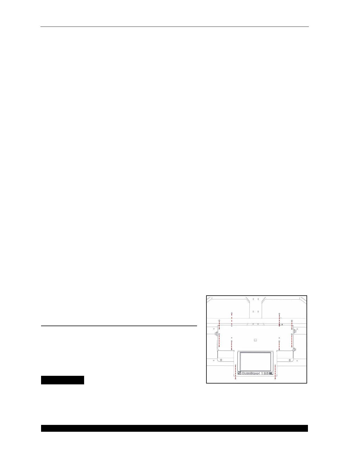
5. Using the 1/8'' Allen wrench, remove the four screws
holding the controller in place. See Figure 39.
6. Pull the controller out.
7. Locate the replacement controller box and place it in
the CubiScan 125 base assembly.
8. Secure the controller using the screws from step 5.
9. Reconnect all the necessary cables to the controller
box. For more information refer to step 3.
10. Replace the ground cable and secure it using the nut
from step 4.
11. Carefully replace the glass platform.
12. Reconnect the power cord from step 1 and power the
CubiScan 125 on.
Replacing the Inverter Board
This section describes how to replace the inverter board.
The inverter board is located inside the controller.
Handle the inverter board with care and avoid exposing
it to static electricity.
Items Needed
• Phillips screwdriver
• Replacement inverter board
Figure 40
Controller Box Screws

 Loading...