Part Replacement Replacing Gate Cables
CubiScan 125 Service Manual 50
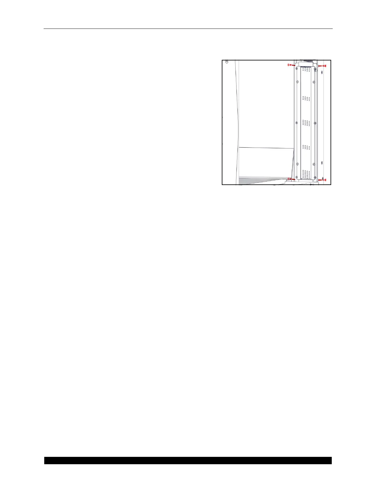
34. Attach the connectors to the ribbon cables. When
you attach the connectors, make sure that you line
pin 1 (the red wire) up with pin 1 on the connector.
35. Route the ribbon cables and gate power cable to the
controller and plug them in. When routing the cables
make sure that they are as far as possible from the
back load cell. If they are routed too closely to the
load cell the CubiScan 125 may not measure
correctly. Do not zip tie the cables in place yet.
36. Replace the encoder and secure it using the screws
from step 7. Tighten the set screws from step 8.
37. Once all the cables have been plugged in turn the
CubiScan 125 on.
38. Go to the first gate diagnostic screen and make sure
that the gate is functioning correctly.
39. Once you have determined that everything is
working properly, the CubiScan 125 is ready to be
put back together.
40. Screw the ribbon cables in place if you have not
already done so.
41. Replace the bubble level cover and secure it using the
screw from step 9.
42. Replace the platter and secure it using the 20 screws,
10 in front and 10 in back, from steps 3 and 4. Do not
tighten these screws individually, partially tighten all
of the screws before tightening them all the way.
43. Replace the glass platform.
44. You will then need to align the gate. You will need
the calibration cube. Make sure you are still in the
first gate diagnostic screen. Place the calibration
cube in various places on the glass platform,
measure them, and check the heights that are
reported. The heights should all be within 0.4''
tolerance of each other. If the various heights are not
within this tolerance, move the gate up or down until
they are all within tolerance. The gate should only
need to be adjusted in slight increments. Once you
have adjusted the gate and all measurements are
within tolerance, tighten the bolts from step 14.
Make sure you tighten the bolts with washers first.
Figure 64
Height Transmitter Board Assembly
 Loading...
