Page 11 of 133
Version 3.0 REV r000
Date 25-08-2010
List of Figures
Figure 1: Sonic 2024/2022 Block Diagram ............................................................................................ 15
Figure 2: Sonic 2024 Acoustic Centre ................................................................................................... 19
Figure 3: Sonic 2024 Acoustic Centre as Mounted ............................................................................... 19
Figure 4: Sonic 2022 Acoustic Centre ................................................................................................... 20
Figure 5: Sonic 2022 Acoustic Centre as Mounted ............................................................................... 20
Figure 6: Sonic 2024 and Sonic 2022 on the mounting frame ............................................................. 21
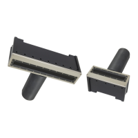
Figure 7: Top side of Receive Module .................................................................................................. 22
Figure 8: Receive Module Face ............................................................................................................. 22
Figure 9: Receive Module securing bolt ............................................................................................... 22
Figure 10: Insert short threaded side of bolt in pass-through and tighten to receiver face ................ 22
Figure 11: Seated connectors (Sonic 2024 on left and Sonic 2022 on right) ...................................... 23
Figure 12: Receive Module with cables connected .............................................................................. 23
Figure 13: Position the insulating bushing, then wrap threads with Teflon tape, then secure with flat
washer, locking washer and then nut .................................................................................................. 23
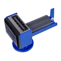
Figure 14: Sonic 2024 Projector ........................................................................................................... 24
Figure 15: Projector Stand-off .............................................................................................................. 24
Figure 16: Mounting the projector ....................................................................................................... 24
Figure 17: View of the mounted Projector; NB. Connector is facing protective fin ............................. 25
Figure 18: Correct Orientation of the Sonic 2024 and the Sonic 2022 ................................................ 25
Figure 19: Typical over-the-side mount ............................................................................................... 26
Figure 20: Single Head ROV Installation scheme A .............................................................................. 31
Figure 21: Single Head ROV Installation scheme B (Preferred) ............................................................ 31
Figure 22: Dual Head ROV Installation scheme A ................................................................................. 32
Figure 23: Dual Head ROV Installation scheme B (Preferred) .............................................................. 32
Figure 24: Sonar Interface Module (SIM) ............................................................................................. 33
Figure 25: Removal of trim to expose securing holes .......................................................................... 34
Figure 26: SIM Interfacing Physical Connections ................................................................................. 35
Figure 27: SIM Interfacing Guide (from label on top of the SIM) ......................................................... 35
Figure 28: SIM IEC mains connection and deck lead Amphenol connector ......................................... 36
Figure 29: Impulse connector ............................................................................................................... 36
Figure 30: Sonic Control Icon on desktop ............................................................................................. 39
Figure 31: Sonic Control 2000 .................................................................................................
............. 39
Figure 32: Windows XP Internet Properties ......................................................................................... 40
Figure 33: IP and Subnet mask setup ................................................................................................... 41
Figure 34: Sonic Control Network setup .............................................................................................. 42
Figure 35: Command prompt-ipconfig/all ........................................................................................ .... 43
Figure 36: Sensor communication settings .......................................................................................... 44
Figure 37: Sonar Operation Settings window ....................................................................................... 45
Figure 38: Operating Frequency Selection ........................................................................................... 46