Racepak
30402 Esperanza, Rancho Santa Margarita, CA 92688 USA
Phone: 949-709-5555 Fax: 949-709-5556 www.racepak.com
11
Configuration File (setup file)
Viewed by opening the car configuration file by one of the below methods:
• Standalone –FileOpen Car ConfigurationSmartWireClick OK
• Via Data Recorder – FileOpen Car ConfigurationThe data recorderClick OK
NOTE: When via Data Recorder, the SmartWire channels will only appear after the SmartWire
has been connected and synced up with the data recorder by performing a Read V-Net Config.
NOTE: If optional Switch Panel and/or Switch Module is installed, a separate channel, for each,
may appear with what is shown below. See Switch Panel Section for programming details.
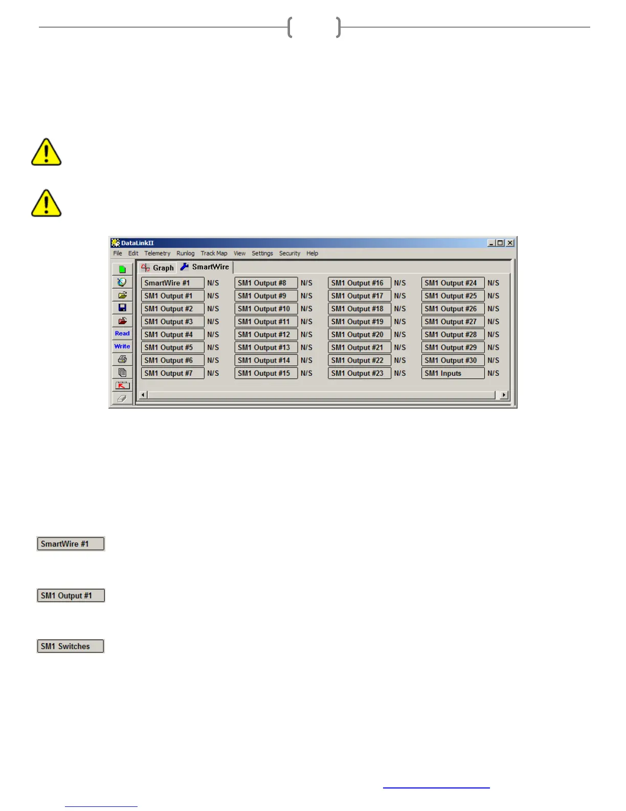
Next to the graph tab, a tab appears with a blue wrench. This blue wrench designates the configuration file tab.
Listed below the configuration tab are the buttons for each of the channels on the SmartWire unit.
Channel buttons:
By right-clicking on each channel button, the channel settings for that particular channel are available.
SmartWire#1: Channel button to access the SmartWire main unit system settings (SmartWire
Parameters)
SM1 Output #1 – SM1 Output #30: Output channels 1-30. Each of these buttons accesses the
channel settings for each SmartWire output. See inside back cover for pin locations on main connectors.
SM1 Switches: Hardwired input switches to SmartWire unit, input channels 1-12. This channel
button contains the settings for each of the 12 input connections to the SmartWire. See inside back cover for pin
locations on main connectors.