Racepak
30402 Esperanza, Rancho Santa Margarita, CA 92688 USA
Phone: 949-709-5555 Fax: 949-709-5556 www.racepak.com
20
Logic Example
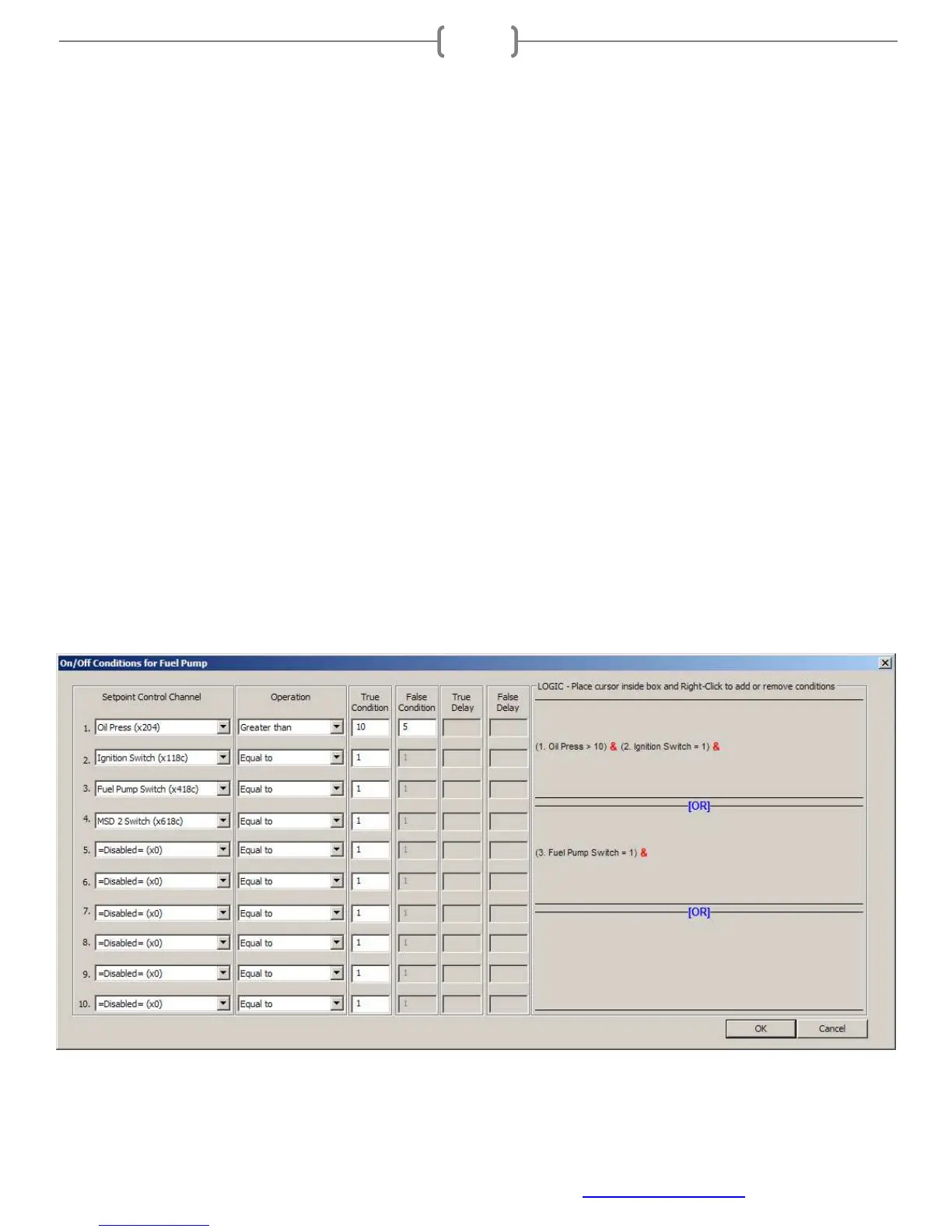
The example below is for an output connected to a Fuel Pump. An Oil Pressure sensor is installed via V-Net.
The Ignition Switch, Fuel Pump Switch and MSD 2 Switch are connected via the Switch Panel. The example
shows;
Turn on the output channel (Fuel Pump) when the following conditions are True:
• Oil Press is above 10psi (greater than 10) “&” Ignition Switch is on (equal to 1) “OR” Fuel Pump
Switch is on (equal to 1)
This would turn the pump on anytime the engine has oil pressure “&” the ignition switch is on “OR” the Fuel
Pump Switch is on (equal to 1)
The Fuel Pump would turn on if the fuel pump toggle switch was turned on (True) regardless of any other
conditions. This could be viewed as a “force on” switch possibly used for priming.
The “&” value connects two logic conditions together meaning both would have to be True in order for the
output channel (Fuel Pump) to be activated.
The “OR” value separates the logic conditions. If ANY of the logic conditions are True, the output channel
(Fuel Pump) would be activated and remain on until all logics are False.
NOTE: There is one Setpoint Control Channel (MSD 2 Switch) that is enabled, but not used anywhere in the
logic area; therefore this Setpoint Control Channel will not affect anything on this output channel.
All logic conditions are added/removed by right clicking in the Logic area.