Racepak
30402 Esperanza, Rancho Santa Margarita, CA 92688 USA
Phone: 949-709-5555 Fax: 949-709-5556 www.racepak.com
3
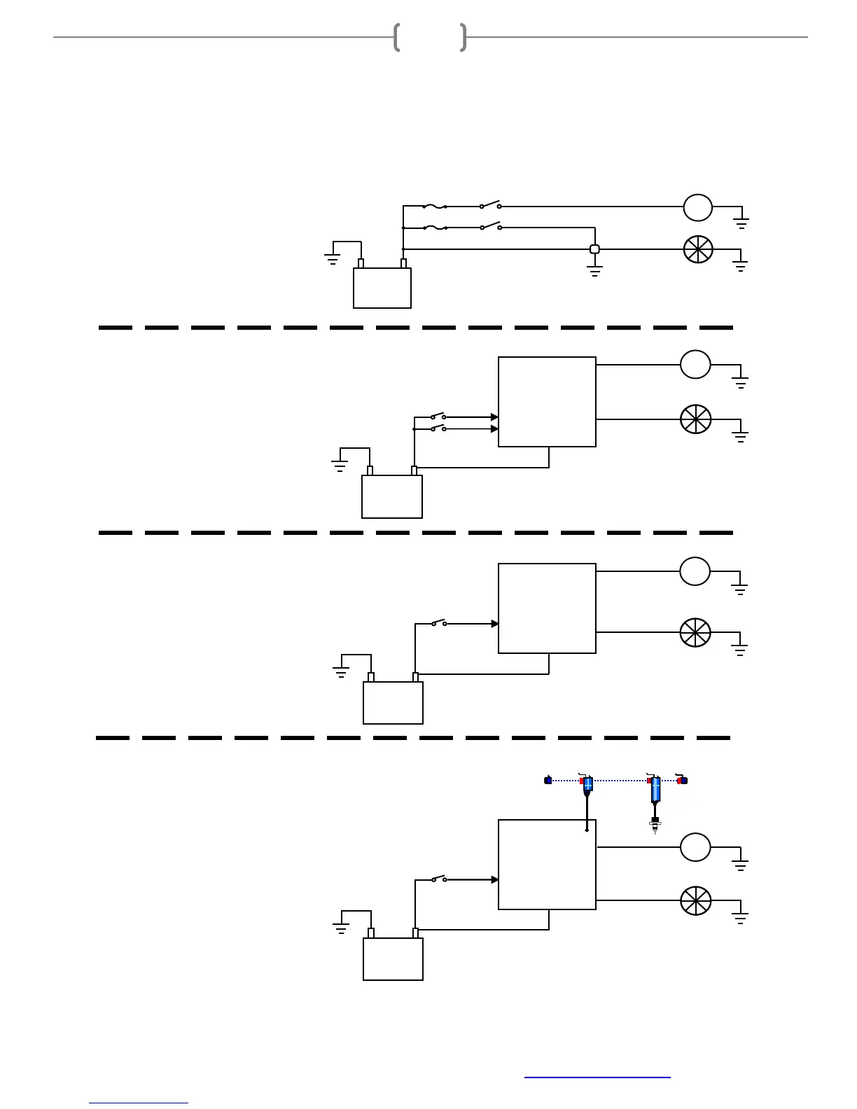
Example Installation Overview
In a standard switch/device application, power is routed to a switch, with this switch controlling one device.
Depending on the device current (Amperage) requirement, this switch controls a relay, when triggered, allows a
large amount of current flow to the device. Activating the device requires manually flipping a switch.
Fan
Water Pump
SmartWire
Unit
Hardwired
Inputs
Battery Input
Two Switches:
One for Water Pump
One for Fan
Battery
Fan
Water Pump
Battery Input
One Switch for both
Battery
SmartWire
Unit
Outputs
V-Net Port
Fan
Water Pump
Battery Input
Battery
One Switch for both:
SmartWire
Unit
Outputs
Water
Temp
Module & Sensor
V-Net to
SmartWire
Tee
Switch
Fuse
Switch
Two Switches:
One for Water Pump
One for Fan
Standard switch installation:
One switch for each device.
Switch on, device on.
Basic SmartWire installation
One switch for each device.
Switch on, device on.
Monitors on both devices for:
•
Current (Amps)
•
Voltage
•
Status (on/off/blown fuse)
Option #1 SmartWire installation
One switch for both devices.
Switch on, both devices on.
SmartWire can toggle both devices on/off at
set timer intervals
Monitors both devices for:
•
Current (Amps)
•
Voltage
•
Status (on/off/blown fuse)
Option #2 SmartWire installation
One switch for manual override, V-Net sensor used
for trigger
Switch on, devices on regardless of temperature
input.
Switch off; SmartWire is programmed to
automatically turn both devices on at user set
temperatures based on V-Net input. SmartWire can
toggle both devices on/off at set timer intervals
Sensor failure, SmartWire can be programmed to
force devices on should temperature go outside
sensor readable scale regardless of switch position.
Monitors both outputs/devices for:
•
Current (Amps)
•
Voltage
Status (on/off/blown fuse)
Hardwired
Input
Hardwired
Input