Racepak
30402 Esperanza, Rancho Santa Margarita, CA 92688 USA
Phone: 949-709-5555 Fax: 949-709-5556 www.racepak.com
32
Input Configuring (Walk through cont.)
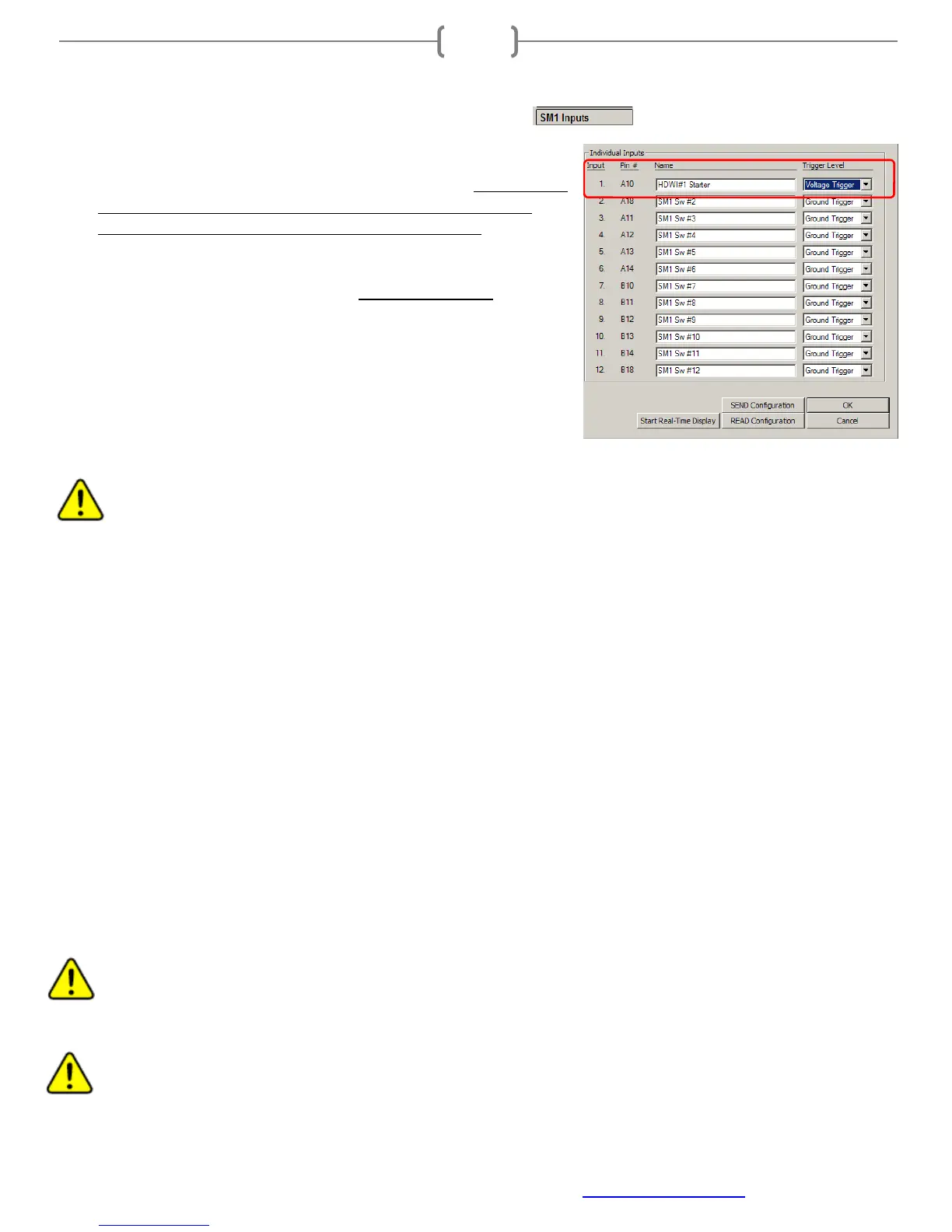
1. Right click on the channel button listed as SM1 Inputs
2. Select an available switch under the Individual Inputss area
(shown right). For this example we’ll use Input 1. Take note of
the Pin # for this input as this will be the pin on the 23 pin
connector used to connect to the button. Pin # A10.
3. In the name, type in a name that repesents what this input will
be. For this example, we’ll type in HDWI#1 Starter. The
name repesents Hardwire Direct Input # 1 Starter, for starter
button. This will make it easy for future reference of this
channel in later programming.
4. Under the Trigger Level area, click on the drop-down arrow
and select the correct “Trigger”, Ground or Voltage. In this
example, the Voltage Trigger should be selected.
NOTE: If this was set for Ground Trigger, should the wire short against ground somewhere
between the SmartWire and the ground source, the starter would engage and stay engaged. For
this application, Voltage Trigger is a safer choice.
5. When set to Voltage Trigger, input channel #1, pin A10 will require a voltage signal greater than 4 volts to
be applied to trigger this input. Considering this is for a Starter, a momentary button conencted to a power
source will be used to trigger the input.
6. Once the name and trigger level has been set, we can send this change to the SmartWire by clicking the
“SEND Configuration” button in the lower center area of the window.
7. A message log window will open and start to scrolling indicating writing to the SmartWire is in progress.
8. Once completed, the message log window will show “DEVICES PROGRAMMED
SUCCESSFULLY”.
9. Click OK and at this point, returned to the SM1 Inputs window.
10. Click OK on the SM1 Inputs window to return to the main configuration window.
11. At this point, terminate the A10 pin to a momentary pushbutton and wire the other side of the button
battery power or terminate this at a later date.
Note: Depending on how many outputs planned on using, it is possible to wire to another output
from the SmartWire and trigger this output with an ignition switch programmed in a similar
fashion.
Note: If the input pin is wired at this point, click the “Start Real-Time Display” button to verify the
signal when pressed. Since output is not configured at this point for this input, no activities occur.