Racepak
30402 Esperanza, Rancho Santa Margarita, CA 92688 USA
Phone: 949-709-5555 Fax: 949-709-5556 www.racepak.com
33
Output Configuring (Walk through cont.)
An output channel will now need to be configured for the starter button input. This channel will activate the
starter solenoid on the starter motor. Select an output with an appropriate current (Amps) rating by referring to
the Channel Pin Chart located on the inside of the rear cover of this manual. The starter solenoid in most cases
can draw up to 20 Amps. For this example, we’ll select Output #1 Pin A3
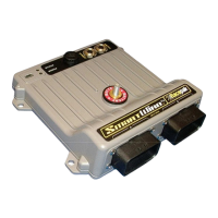
1. In the main configuration window, right click on the channel button SM1 Output #1
2. The first thing that should be done is to confirm this paticular channels
capacity is rated higher than the operating current (Amps) of the device
that it is connected to. This is noted by verifing the Type: located in the top right corner of the window.
20A
3. In the Channel Name text box, type in a name that repesents what this
input will be. For this example, we’ll type in O#1 Starter Solenoid.
The name repesents Output # 1 Starter for which the output will connect to. This will make it easy for
future reference of this channel in later programming.
4. Take note of the Pin # for this input as this will be the pin on the 23 pin connector used for this button.
This Pin # is located in the bottom left corner of the window. Pin# A3
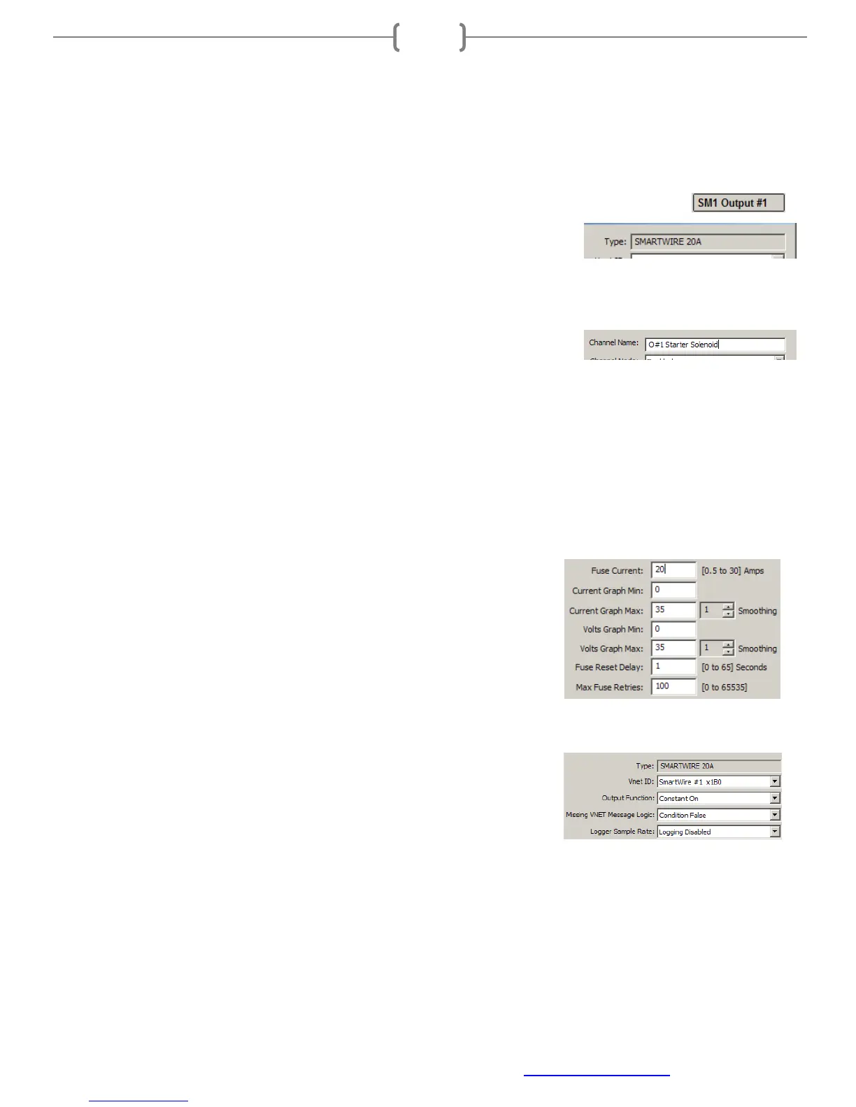
5. Verify and set the values for the output channel. These should be set to match the output connecting to.
Below are values that specifically require attention.
• Fuse Current: Setting this value below or slightly above the normal
operating current of the device this output is connected may result in
inadvertent shutdown of this output. These values should be set
higher than normal operating current. The purpose of this is to
protect the wire from overheating should the device fail. Some
devices can draw more current under certain situations such as low
battery voltage and increased demand/load.
• Fuse Reset Delay / Max Fuse Retries: When an over-current or
blown fuse situation occurs, the SmartWire will attempt to reactivate
the output. The Fuse Reset Delay determines the amount of time
after the fuse has blown before the output is re-activated. The Max
Fuse Retries determines the how many times the SmartWire will
attempt to reactivate the output.
• Output Function: This sets the function of the output. Select the
one that most represents the desired output. In most cases where on/off is the desired function, as in this
example, Constant On should be selected.
6. Once these values are set, we can send this change to the SmartWire by clicking the “SEND
Configuration” button in the lower right area of the window.
7. A message log window will open and start to scroll indicating writing to the SmartWire is in process