Racepak
30402 Esperanza, Rancho Santa Margarita, CA 92688 USA
Phone: 949-709-5555 Fax: 949-709-5556 www.racepak.com
4
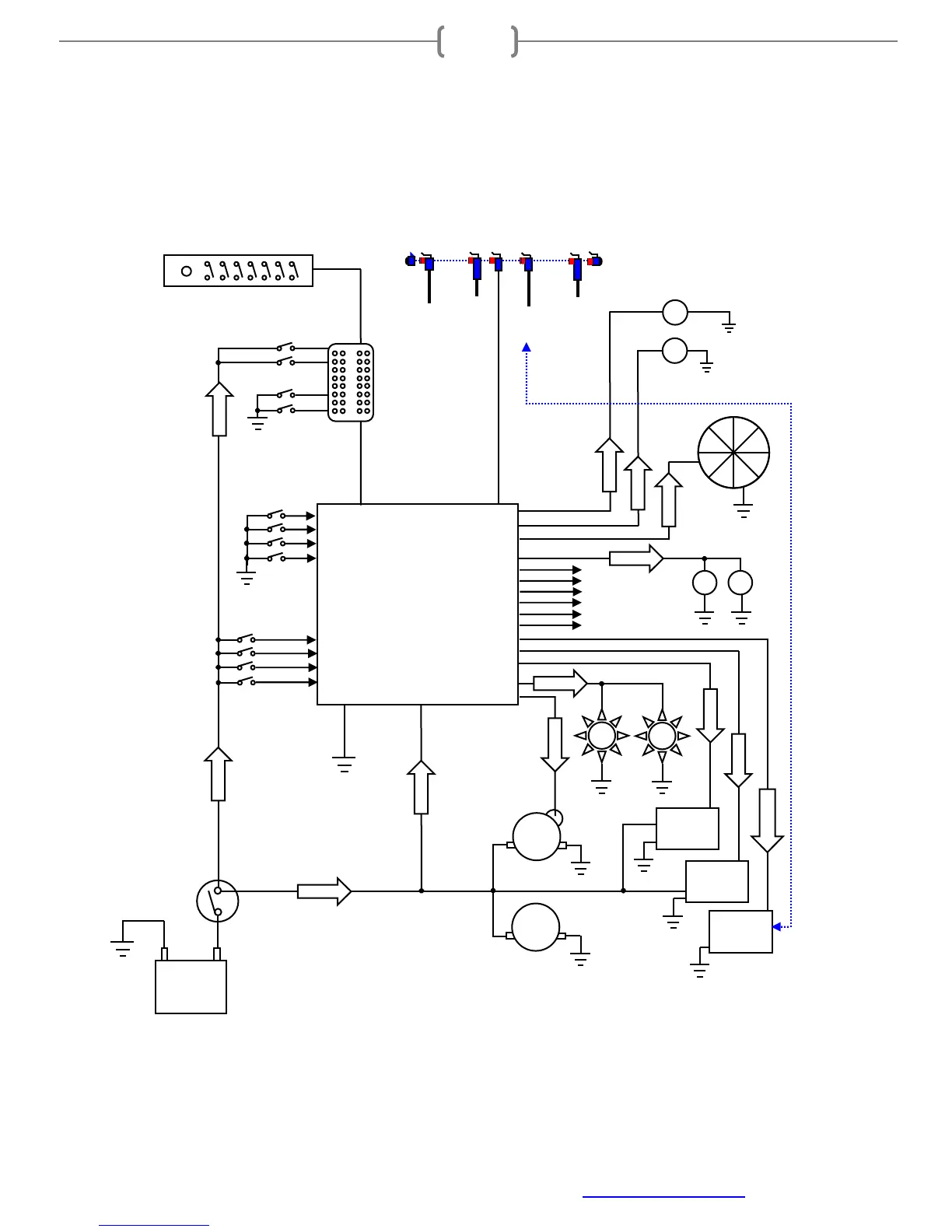
Option #3 SmartWire installation in conjunction with Racepak V-Net data recorder
When connected to a V-Net data recorder, each sensor can be utilized for on/off function or logic control of
each device connected to the SmartWire. Optional Racepak Switch Panels or Switch Modules can also added
and connected to the SmartWire for more inputs and/or control.
Main Power from Battery
or cut-off switch
Battery
Cut-Off
Switch
Alt
SmartWire
Unit
Hardwired Inputs
Outputs
Battery Input
Main stud
Optional Switch
Panel Inputs
Voltage
triggered
Switches
Solenoids
Fan
Fuel Pump
Outputs to
additional
devices
Lights
Ground triggered
switches
Voltage triggered switches
Optional Switch Panel
Ignition
ECU
Ground
triggered
Switches
Starter
Most ignition and ECU systems require a direct main power connection.
This main power connection must go directly to the battery. DO NOT connect
the main power wire from these devices to the SmartWire outputs. Each of
these devices will also have a small wire requiring an ignition switched power
source. This small wire will connect to an output from the SmartWire.
Optional
V-Net
Inputs
Sensor
Input
To Data
Recorder
To Display
Dash
Sensor
Input
V-Net Data
Recorder
Ground
(3 wires)
Water pump
Starter
Solenoid
Switch port
V-Net port
Optional
Switch
Module