Radiolink Electronic Ltd
www.radiolink.com
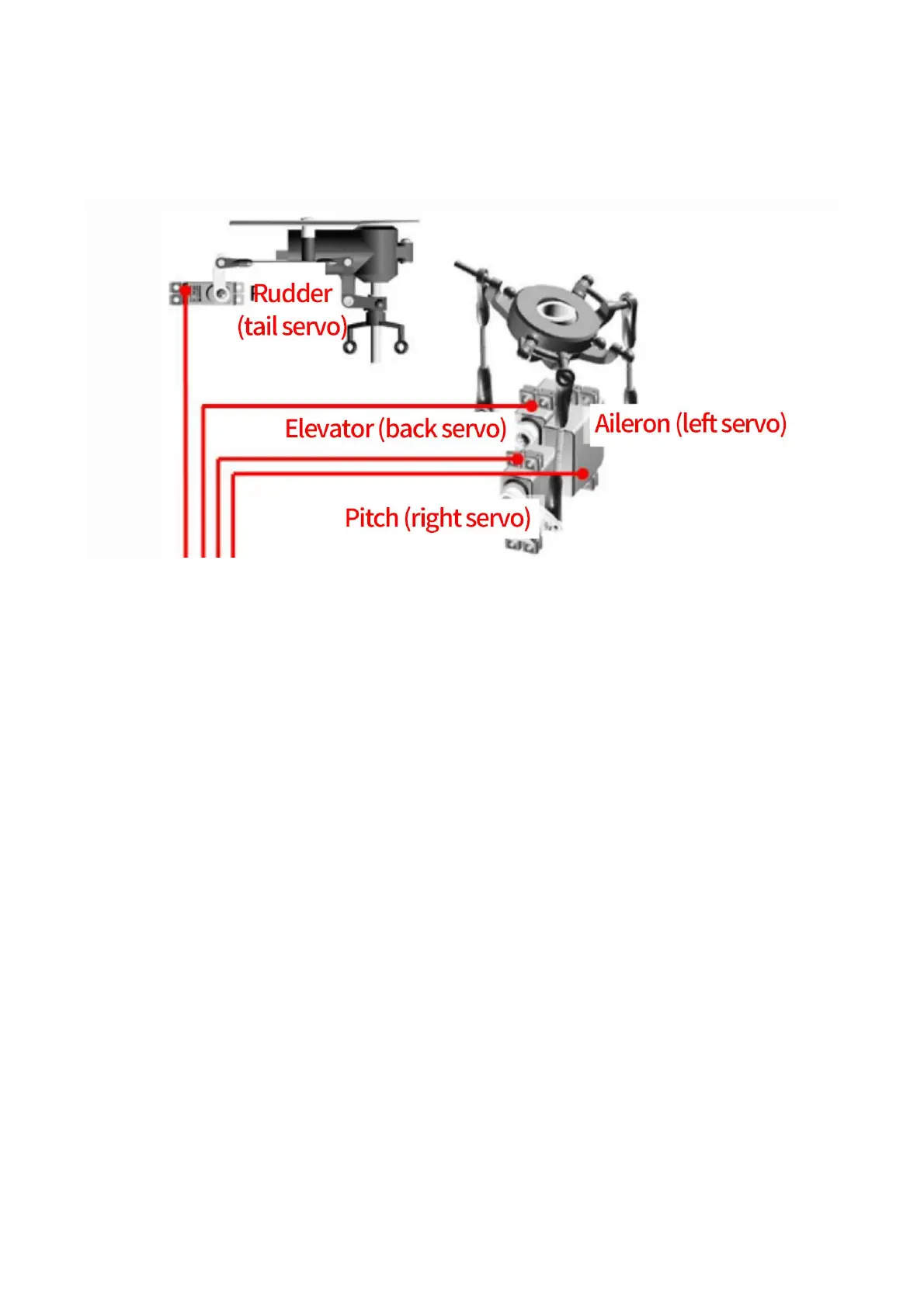
5.2 Connect CrossFlight to Helicopter
Crossflight connection instructions:
Crossflight ESC1 -- aileron, left servo
Crossflight ESC2 -- pitch, right servo
Crossflight ESC3 -- elevator, back servo
Crossflight ESC4 -- rudder, tail servo,
Crossflight ESC6 -- ESC
Note Since there’s no voltage output from the flight controller, an extra BEC module needs to be connected
to power supply servo for this model frame
5.3 Connect the Spare Parts
Receiver module and buzzer: connect to the flight control RC IN/BUZZER port with the provided 5pin GH
plug-in cable.
Power Module: use a 6-pin GH wire to connect the power module to the POWER port of the CrossFlight.
GPS and compass: use a 6-pin GH wire to connect the GPS (TS100 for example) to the GPS/I2C port of
the CrossFlight, please make sure that GPS keeps the same direction as CrossFlight.