Radiolink Electronic Ltd
www.radiolink.com
5.5 Helicopter Setup
Before your first flight, please follow these pre-flight checks:
1. Disconnect the three connecting wires between the ESC and the motor to ensure that the armed motor will
not rotate.
2. Connect lithium battery for power supply.
3. Connect the flight controller and Mission Planner on computer via USB.
4. Open SETUP—> Mandatory Hardware——> Heli Setup in Mission Planner.
5. Please note that the output control is only available in Stabilize mode or Acro mode, and the adjustment
test cannot be performed in other modes.
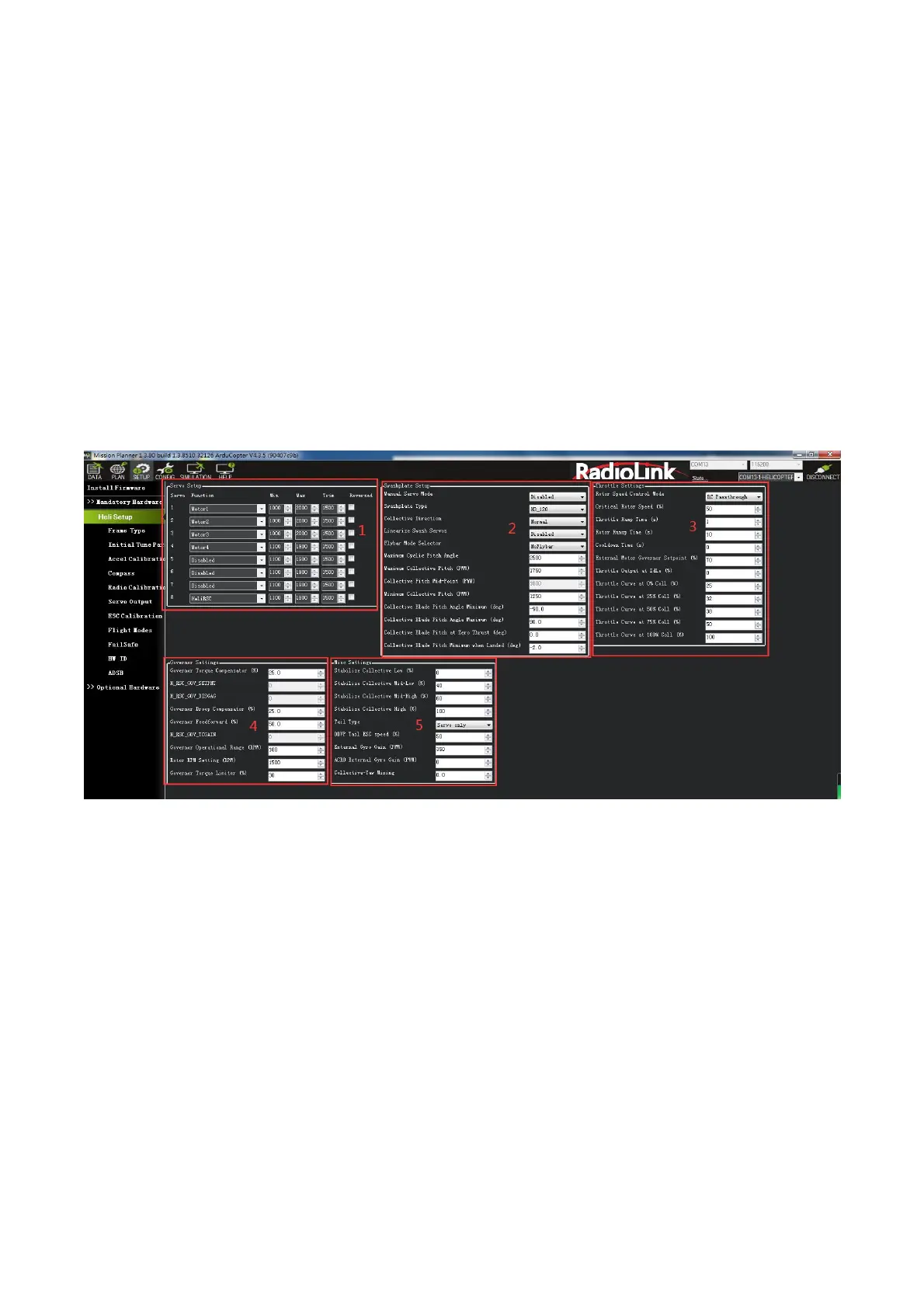
5.5.1 Heli Setup Interface Introduction
Function introduction
1. Servo Setup. The function of each PWM output channel can be set.
2. Swashplate Setup
3. Throttle Settings
4. Governor Settings
5. Misc Settings
5.5.2 Select Swashplate Type
Below are the swashplate type selections using the H_SW_TYPE parameter. The diagrams shown label the
servo attach positions as Servo 1, Servo 2 and Servo 3 for the three servo swashplate types. These also
correspond to the default output functions for servo outputs 1 thru 3 on the autopilot for the servos used with
these swashplate types.
For single heli, the servo function assigned to Servo 1 is motor 33, Servo 2 is motor 34, and Servo 3 is motor
35. These assignments are the same for swashplate 1 for a dual heli frame. Swashplate 2 for a dual heli
defaults to servo outputs 4, 5, and 6 with motors 36, 37 and 38 assigned respectively.