Radiolink Electronic Ltd
www.radiolink.com
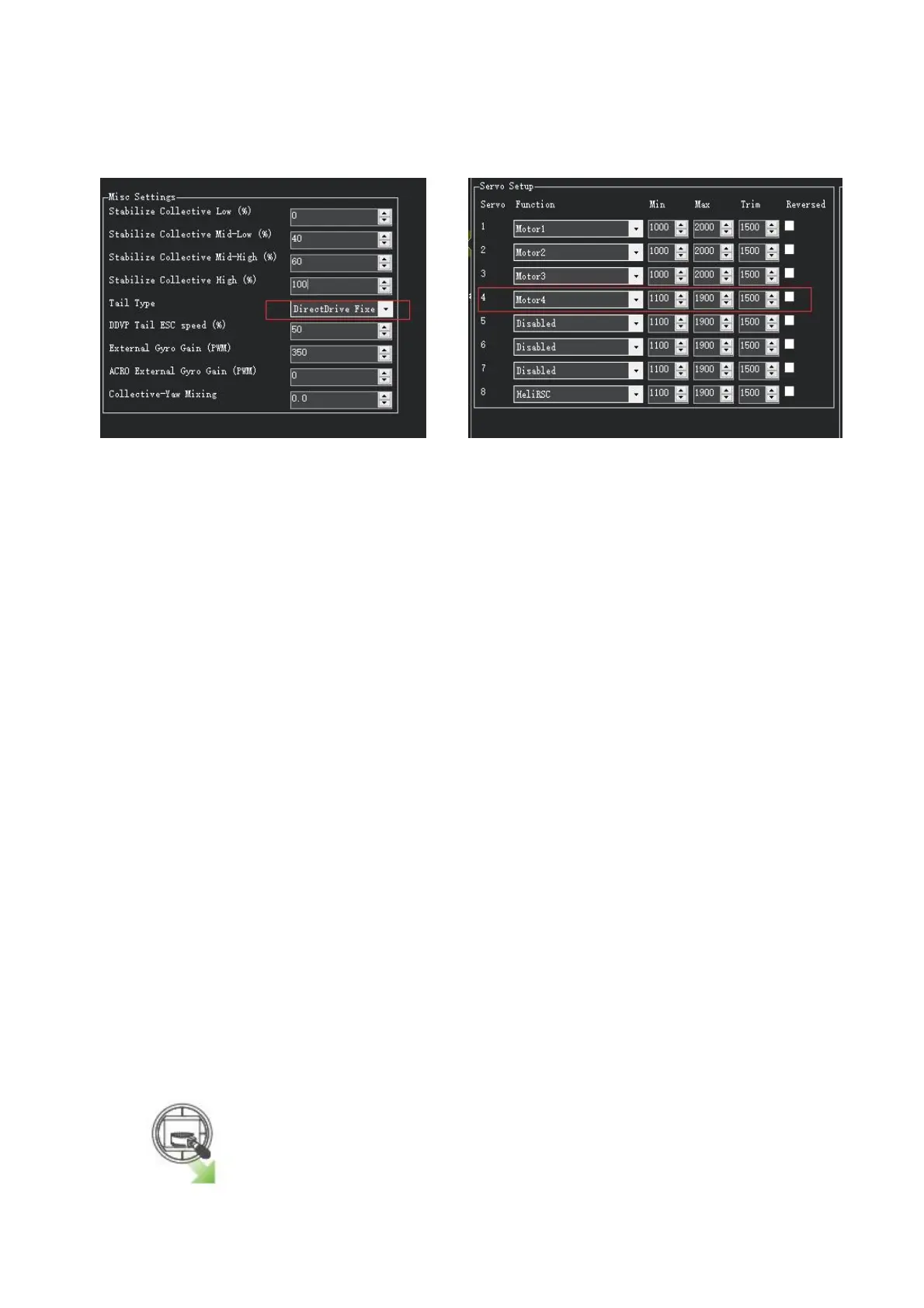
As shown in Figure 10 below, set the parameter SERVOx_FUNCTION to "Motor4" to control the tail motor.
(The default output channel is channel 4.)
Figure 9 Select Direct Drive Fixed Pitch Counter-Clockwise Figure 10 Set Output Channel
6. LED Indicator, Arming and Troubleshooting
6.1 LED Indicator
Blue and red flashing: Initializing
Yellow flashing twice: Error, Arming rejected
Blue flashing: Stabilize, can be armed. Faile to RTL or PosHold
Green flashing: GPS locked, can be armed and take off, RTL
Green always on + a long D sound: Armed and ready to take off
Yellow flashing: Transmitter failsafe activated
Yellow flashing+repeated sounds: Battery failsafe activated
Yellow flashing+High/High/Low sounds: GPS data error or GPS failsafe activated
6.2 Arming and Disarming
Connect all the accessories. When you have completed transmitter calibration, acceleration calibration and
compass calibration, you can try to arm it.
When the LED of the flight controller is blue or green, it can be armed. You can only arm or disarm in
Stabilize, ACRO, AltHold, Loiter, and PosHold modes. You cannot arm your copter in AUTO mode.
Arm action:
1.Arm the motors by holding the throttle down, and rudder right for 5 seconds.