Do you have a question about the Rain Bird IQ and is the answer not in the manual?
Explains the meaning of symbols used in the manual for warnings and instructions.
Provides the toll-free number for technical assistance from Rain Bird Technical Services.
Directs users to the official Rain Bird website for support and information.
Provides contact details for Rain Bird Global Support Plan in the U.S. and Canada.
Provides contact details for Rain Bird Global Support Plan in Australia.
Provides contact details for Rain Bird Global Support Plan in Europe.
Provides contact details for Rain Bird Global Support Plan internationally.
Expresses gratitude for purchasing the IQ Network Communication Cartridge (IQ-NCC).
Details the manual's purpose as an addendum to ESP-LX Series Controller guides.
Explains how ESP-LXME and ESP-LXD controllers can be upgraded for the IQ Central Control System.
Describes the IQ Central Control System's capability for remote monitoring of controllers.
Explains how the IQ-NCC cartridge enables ESP-LX controllers to become IQ Satellite Controllers.
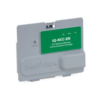
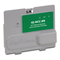
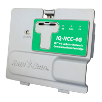
Lists the Rain Bird IQ™ products described in this installation manual.
Defines and differentiates Direct, Server, and Client IQ Satellite Controller configurations.
Details the components included with the IQ Network Communication Cartridge.
Lists required decisions before beginning the installation and configuration process.
Lists the types of IQ Network Communication Cartridges included.
Specifies the required cables for connecting the cartridge to the module.
Details the various cables or antennas for connecting to the IQ computer.
Provides instructions for unlocking and opening the ESP-LX Series Controller cabinet.
Identifies the knock-out location for the IQ Port communication cable.
Identifies the rear knock-out for the IQNet communication cable if a CM module is used.
Steps to remove the knock-out for communication cables.
Instructions for drilling a hole in the LXMM metal case for antenna installation.
Procedure for removing the knock-out hole on the ESP-LX controller plastic case.
Steps to remove the cartridge bay cover from the front panel.
Instructions for connecting the IQ Port cable or antenna to the cartridge.
Details connecting the CM Port cable based on controller configuration.
Instructions for routing cables and connecting the ground wire for NCC-PH.
Steps for cleaning, preparing, and placing the internal antenna.
Procedure for selecting the satellite type (Direct, Server, Client) in the setup wizard.
Instructions for setting the satellite address, noting specific rules for Direct Satellites.
Procedure for selecting the Satellite IQ Port option, especially for RS types.
Guide to selecting 'Server' as the satellite type in the setup wizard.
Instructions for setting the server satellite address, which is typically 001.
Procedure for selecting the Satellite IQ Port option for Server Satellites.
Guide to selecting 'Client' as the satellite type in the setup wizard.
Instructions for setting a unique client satellite address between 002-256.
Procedure for selecting the Satellite Radio Port option.
Explains that software configuration is performed after hardware setup is complete.
Notes that software configuration is only required for Direct and Server Satellites.
Describes the function of the cartridge Reset button.
Explains the meaning of LED states for communication ports.
Displays the status of IQ, Radio, and CM ports for Direct Satellite controllers.
Displays the status of IQ, Radio, and CM ports for Server Satellite controllers.
Displays the status of IQ, Radio, and CM ports for Client Satellite controllers.
Guide to accessing the IQNet Alarms menu to view communication failures.
Instructions on how to clear all alarms from the IQNet Alarm screen.
Details the four types of connection modules that may be installed in the controller.
Describes the Base Module and Flow Smart Module for ESP-LXME controllers.
Steps for removing an existing module and installing a new one.
Procedure for installing the grounding wire for IQ-CM-LXD or IQ-CM-LXME modules.
Steps for installing a SIM card in the IQ-NCC-GP cartridge.
Details compliance with US FCC and Canadian EMC regulations.
Provides safety warnings for analog telephone connections with the PH cartridge.
| Category | Control Systems |
|---|---|
| Connectivity | Wi-Fi |
| Remote Access | Yes |
| Programming | Yes |
| Flow Sensing | Yes |
| Weather Monitoring | Yes |
| Mobile App | Yes |
| Compatibility | Rain Bird sensors and accessories |
| Weather Adjustment | Yes |
| Power Source | 24VAC |
| Watering Restrictions | Yes |
| Warranty | Varies |
| Type | Smart Irrigation Controller |