Common Measurement Settings
R&S
®
FSVA3000/ R&S
®
FSV3000
314User Manual 1178.8520.02 ─ 01
An internal YIG-preselector at the input of the R&S FSV/A ensures that image frequen-
cies are rejected. However, this is only possible for a restricted bandwidth. To use the
maximum bandwidth for signal analysis you can disable the YIG-preselector at the
input of the R&S FSV/A, which can lead to image-frequency display.
Note that the YIG-preselector is active only on frequencies greater than 7.5 GHz.
Therefore, switching the YIG-preselector on or off has no effect if the frequency is
below that value.
Note:
For the following measurements, the YIG-Preselector is off by default (if available).
●
I/Q Analyzer
●
GSM
●
VSA
Remote command:
INPut<ip>:FILTer:YIG[:STATe] on page 923
Preselector Adjust
Activates or deactivates the preselector adjustment.
This function is only available for instrument modelsR&S FSV/A43/50/67/85, for fre-
quency sweeps in the Spectrum application.
Generally, sweeps exceeding a certain span use different signal paths to measure the
required spectrum. In order to minimize the hysteresis impact of the YIG preselector at
the transition frequencies, you can activate this function. It is applied only when the
YIG-preselector is active.
If activated, the R&S FSV/A automatically performs a short internal adjustment. If you
change the frequency or span settings, the adjustment is repeated.
If activated, "PRADJ" is indicated in the window title bar.
Remote command:
CALibration:PADJust[:STATe] on page 922
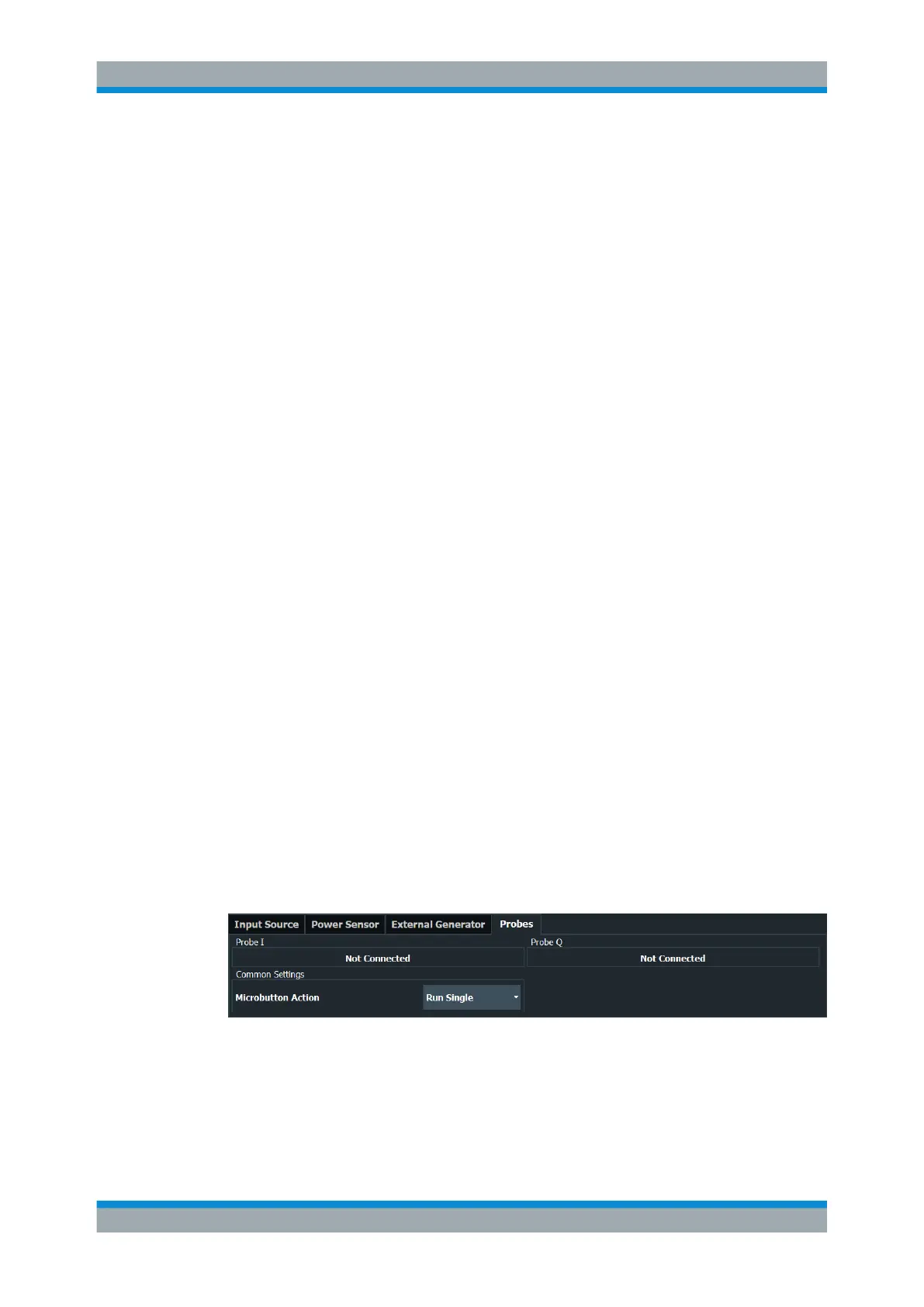
8.2.2.2 Probe Settings
Access: [INPUT / OUTPUT] > "Input Source Config" > "Probes"
Data input for the measurement can be provided by probes if the optional R&S RT-ZA9
adapter is used.
The detected type of probe, if any, is displayed.
For more information on using probes with an R&S FSV/A, see Chapter 8.2.1.1, "Using
Probes", on page 307.
For general information on the R&S
®
RT probes, see the device manuals.
Data Input and Output