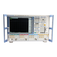
Repairs R&S ZVA
1177.5333.02 3.108 E-11
With the stated levels, the cable loss must still be taken into account. For the specified cable it is
0.25 dB/GHz.
If the measured values are more than 2 dB below the levels in the table, the coupler unit must be
replaced.
Method 2:
The receiver section of the associated reflectometer is OK.
Loosen cable W514 (GEN -> coupler unit) at both ends and screw off at the coupler unit.
Connect the coupler input (connector. W514) to a functioning port using the SMA cable.
Screw the SHORT from the calibration kit to the port connector, save measured values (Data ->
Mem).
Screw the OPEN from the calibration kit to the port connector.
Select User Def Math : (lin Mag(Data) + (linMag(Mem2)) / 2 , activate Result is Wave Quantity
Select Math = User Def
Set the frequencies and levels listed in the table at the port used for the measurement and measure
the level (wave quantity ax or bx) at the reflectometer associated with the coupler unit (port).
With the stated levels, the cable loss must still be taken into account. For the specified cable it is
0.25 dB/GHz.
If the measured values are more than 2 dB below the levels given in the table, the coupler unit must be
replaced.

 Loading...