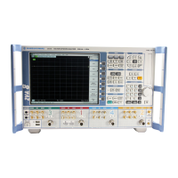
R&S ZVA Repairs
1177.5333.02 3.67 E-11
Replacing the Coupler Unit (ZVA24, ZVA40, ZVA50, ZVA80-BU port1
and port2)
(See Chapter 5, Spare Parts List, item 230 and drawing 1145.1110)
Opening the instrument and removing the coupler
Turn off the instrument and disconnect from the mains, screw off the 4 rear-panel feet (460) and
pull off the enclosure (400) backwards.
Remove the instrument base cover (297) after undoing the screws (299).
Disconnect the 3 RF cables and the bias cable from the coupler
Remove the 3.5mm connection cables (only with option ZVA24-B16).
Remove the frontcover
Remove the screws (182, 186, 202, 206) in the front of the instrument next to the port connector
and take out the coupler.
Fitting the new coupler unit and reassembling the instrument
Insert the coupler into the instrument and screw in the 4 screws (181, 186, 220).
Reconnect the 3 RF cables and the bias cable.
Fit the 3.5mm connection cables (only with option ZVA24-B16).
Fit the instrument base cover (297) and secure with 12 countersunk screws (299).
Push the enclosure (400) back on and screw the 4 rear-panel feet (460) into position.
Connect the mains cable, turn on at the mains switch and press the ON key.
Select Service Level 2 (see Service Functions).
When the instrument has been started, check the protocol file for errors:
[ INFO : Error Log ]
Record generator and receiver correction data (see Recording Correction Data).
Perform factory system error calibration (see Factory System Error Calibration).

 Loading...