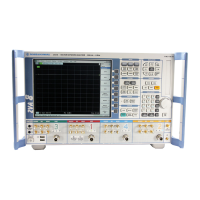
R&S ZVA Repairs
1177.5333.02 3.51 E-11
Replacing Power Supply A20
(See Chapter 5, Spare Parts List, Items 790 and drawings 1145.1110, 1145.1290, 1145.1310)
The power supply is installed at the rear of the instrument frame.
Removing the power supply
Turn off the instrument and disconnect from the mains, screw off the 4 rear-panel feet (460) and
pull off the enclosure (400) towards the rear.
Remove the 4 screws (792) in the rear panel.
Pull out the power supply unit a little at the rear of the instrument, remove screw (737) and anti-
touch guard (736).
On the left-hand side of the power supply, pull off the protective conductor cable and fuse board
(735) to the left.
On the right-hand side of the power supply, remove the plug-on connections to the motherboard.
Remove the power supply unit.
Installing the new power supply
Fit the new power supply by reversing the removal procedure
If you refit a power supply 1145.5238, fit the cables from the removed one to the new one (see
drawing 1145.1290)
Push the enclosure (400) back on and screw the 4 rear-panel feet (460) into position.
Connect the mains cable, turn on at the mains switch and press the ON key.
Select Service Level 2 (see Service Functions).
When the instrument has been started, check the protocol file for errors
[ INFO : Error Log ]

 Loading...