Layout and function 2
6
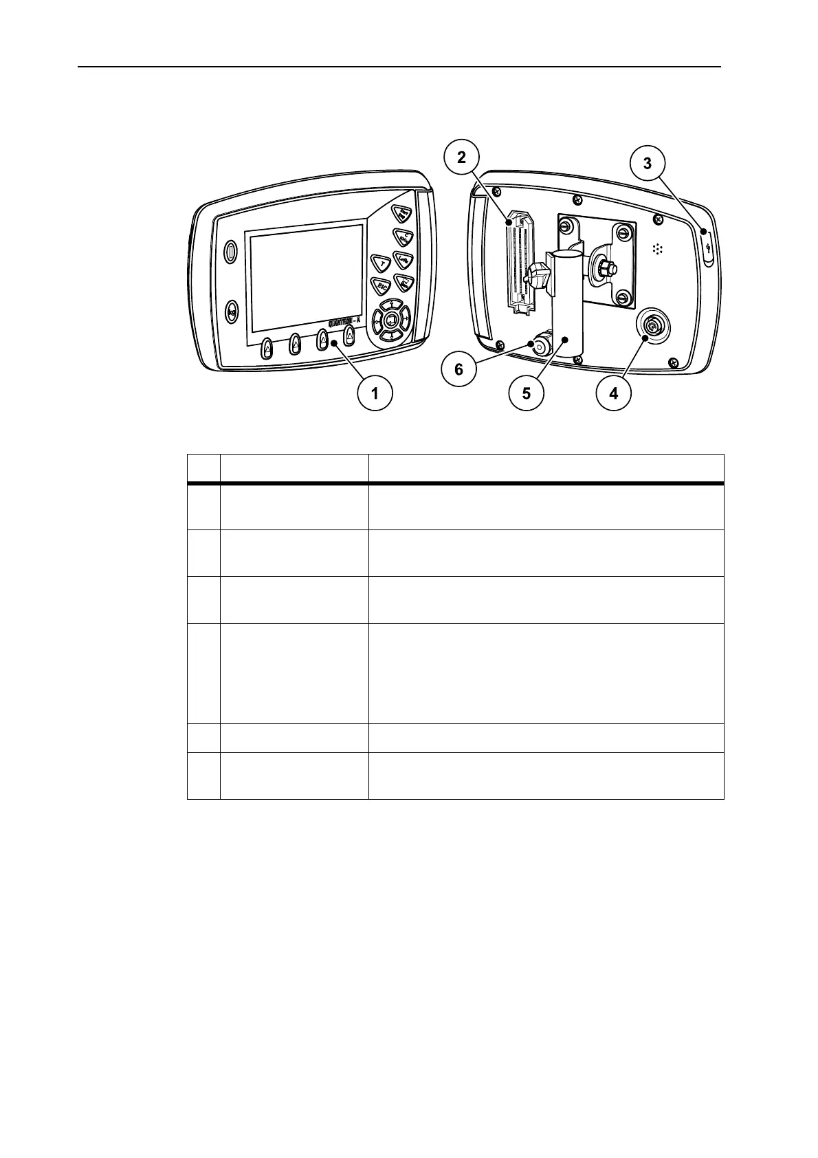
2.2 Layout of the control unit - overview
Figure 2.1: Control unit QUANTRON-A
No. Designation Function
1 Control panel Consisting of foil buttons used to operate the device
and the display for operating screens.
2 Machine cable plug
connector
39-pin plug connector for connecting the machine
cable to sensors and actuating cylinders.
3 USB port with cover For updating the PC. Cover serves as a protection
against contamination.
4 V24 data port Serial interface (RS232) with LH 5000 and ASD pro-
tocol, designed for Y-RS232 cables for connection to
a remote terminal.
Plug connector (DIN9684-1/ISO11786) for 7-pin to
8-pin cable connection for the speed sensor.
5 Mounting bracket Attaches the control unit to the tractor.
6 Power supply 3-pin plug connector conforming to DIN 9680 /
ISO 12369 for connecting the power supply.
 Loading...