4
Manual No. 016-5034-004 33
Wheel Angle Sensor Installation
7. Install the rotary sensor (P/N 416-0001-050) on the sensor mounting bracket (P/N 107-0171-982) using two
#8-32 UNC x 1-3/4” screws (P/N 311-0001-027) and two #8-32 nylon insert lock nuts (P/N 312-4000-053).
Note: The sensor’s connector should point toward the base of the bracket.
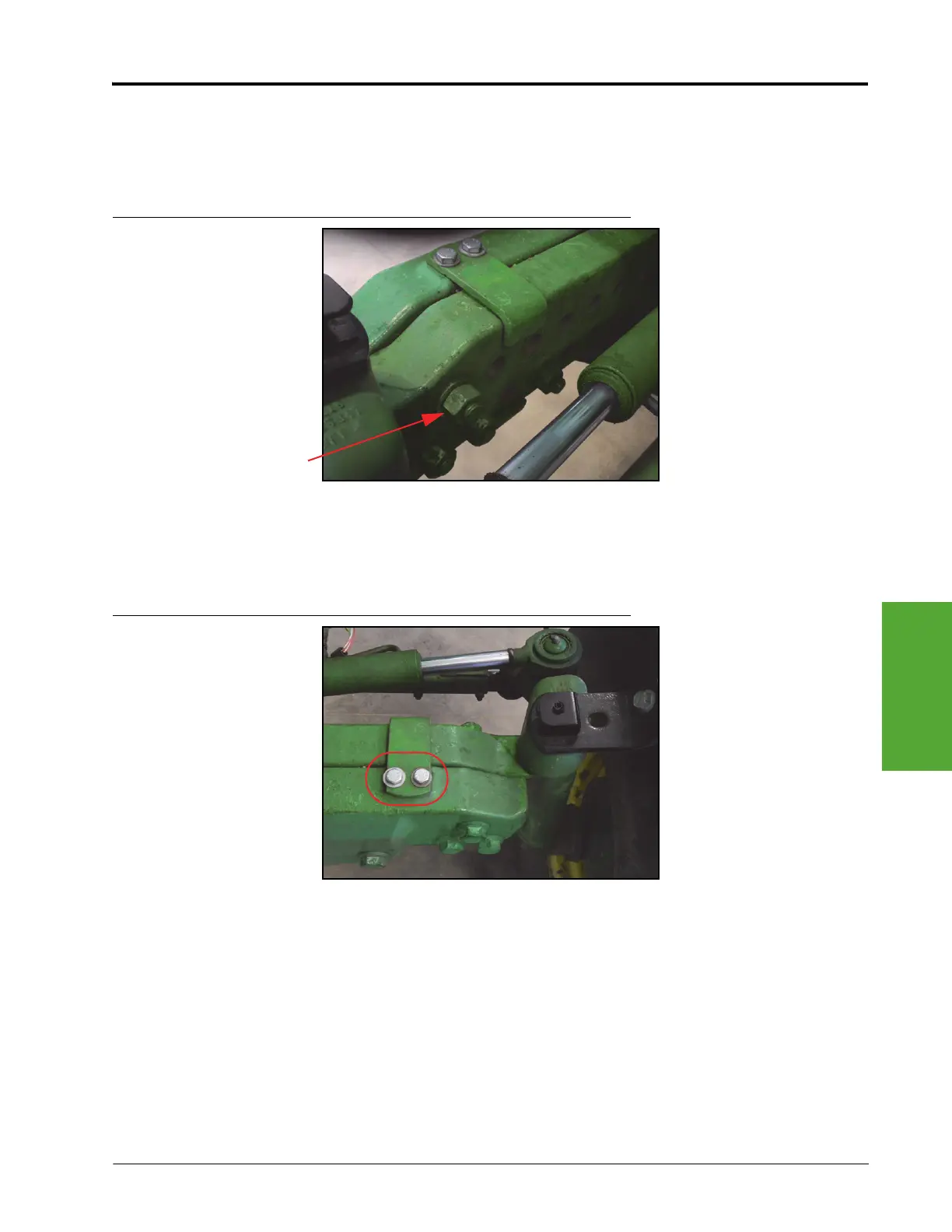
FIGURE 17. Axle Setting
8. Check the front axle setting.
• If the top axle bolt is on setting 1 or 2, proceed to step 9.
• If the top axle bolt is on setting 3 thru 7, skip to step 15.
FIGURE 18. M10 Axle Clamp Bolts
9. Remove the two M10 axle clamp bolts from the top axle clamp.
 Loading...


