Chapter 2: Installing the system 19
3. Drill two 6 mm (1/4”) diameter clearance holes through the center line of the tiller
at the positions marked.
4. Attach the tiller bracket using two 6 mm (1/4“) diameter bolts, nuts and washers.
5. Fix the bolts in position using two-part epoxy adhesive.
6. When the epoxy is completely hardened, fully tighten the nuts.
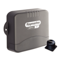
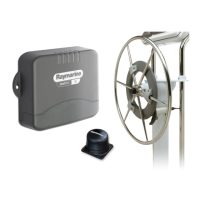
2.6 Connecting power & drive cables to the Course
Computer
Power supply
The SPX-5 Tiller system needs a 12 V dc supply.
CAUTION: Ensure correct supply voltage
Do NOT connect 24 V to the Course Computer, or damage to the
product could occur.
Circuit breaker/fuse
Protect the power supply for the SPX-5 Tiller system with a 10 A fuse or circuit
breaker.
Cable
Using the information given at
Power cable requirement
on
page 8
, obtain the
required length of the appropriate cable to connect power from the boat’s distribution
panel to the Course Computer.
D8815_2
90 degrees
457 mm (18 in)
 Loading...