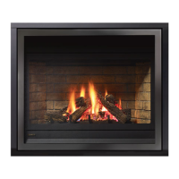
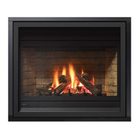
P36E-10 Zero Clearance Direct Vent Gas Fireplace | 35
35
|
installation
GAS LINE
INSTALLATION
The gas line is brought through the right of the ap-
pliance. The gas valve is situated on the right hand
side of the unit and the gas inlet is on the right hand
side of the valve.
The gas line connection may be made of rigid pipe,
copper pipe or an approved ex connector. (If you
are using rigid pipe, ensure that the valve can be
removed for servicing.) Since some municipalities
have additional local codes it is always best to consult
with your local authorities and the CAN/CGA B149
installation code.
For USA installations follow local codes and/or the
current National Fuel Gas Code, ANSI Z223.1.
When using copper or ex connectors use only ap-
proved ttings. Always provide a union so that gas
lines can be easily disconnected for servicing. Flare
nuts for copper lines and ex connectors are usually
considered to meet this requirement.
Important: Always check for gas leaks with a
soap and water solution or gas leak detector.
Do not use open ame for leak testing.
P36E-NG10 System Data
For 0 to 4500 feet altitude
Burner Inlet Orice Sizes: #37
Max. Input Rating: 29,500 Btu/h Min.
Input Rating: 19,500 Btu/h
Supply Pressure: min.5.0" w.c.
Manifold Pressure
(High): 3.5"+/- 0.2"w.c.
Electrical: 120 V A.C. System.
Circulation Fan: variable speed 130 CFM.
Log Set: Ceramic bre, 7 per set.
Vent System: Simpson Dura-Vent Direct
Vent System or Regency Direct Vent System
(Flex)
P36E-LP10 System Data
For 0 to 4500 feet altitude
Burner Inlet Orice Sizes: #52
Max. Input Rating 28,500 Btu/h
Min. Input Rating 22,000 Btu/h
Supply Pressure min.11.0" w.c.
Manifold Pressure
(High) 10"+/- 0.2" w.c.
Electrical: 120 V A.C. System.
Circulation Fan: variable speed 130 CFM.
Log Set: Ceramic bre, 7 per set.
Vent System: Simpson Dura-Vent Direct Vent
System or Regency Direct Vent System (Flex)