P36E-10 Zero Clearance Direct Vent Gas Fireplace | 49
49
|
installation
CAUTION: Label all wires prior to disconnection
when servicing controls. Wiring errors can cause
improper and dangerous operation.
Caution: Ensure that the wires do not touch any
hot surfaces and are away from sharp edges.
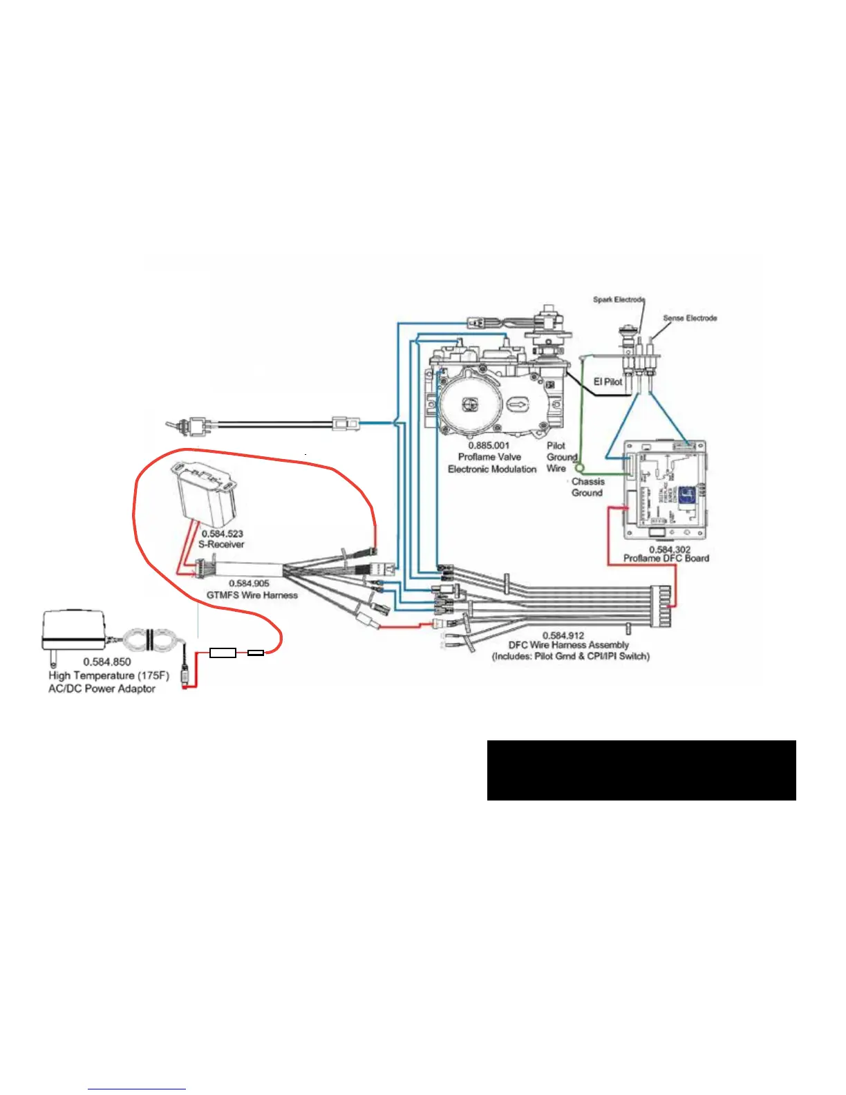
Proflame System
Configuration
886 GTMF
Wire Diagram
SureFire™ Switch
885
AC Adaptor
WIRING DIAGRAM
This heater does not require a 120V A.C. supply for operation but it is highly recommended to install the supplied AC adaptor to eliminate the need for
batteries. In case of a power failure, the burner switch and the optional remote control will continue to operate if batteries are installed in the receiver..
However, a 120V A.C. power supply is needed for the fan/blower operation.
(Do not cut the ground terminal o under any circumstances.)
NOTE: Even if the fan is not purchased with the unit, it is still a good idea to bring power to the receptacle box (provided with the unit) in case
the fan is installed at a later date.