IN-7900
11
2.6. Refractor Arm - Dual Lock
2.6.1. Unpack the Refractor Arm. Slide the Clamp Sleeve
carefully down over the Support Column until positioned as
shown in Figure 1. Tighten the clamp screw securely, using
the hex key wrench provided.
2.6.2. Note that the chrome Plug Button in the front of
the Refractor Arm Assembly covers the counterbalance
spring adjusting screw. If necessary, after the Instrument
is attached to the Refractor Arm, remove this button and
adjust the screw, turning it clockwise to increase tension.
Optimum adjustment is reached when the Refractor Arm
barely supports the weight at the upper limit of its travel.
The Refractor Arm will support Instruments weighing a
maximum of 20 pounds.
2.7. Overhead Lamp
2.7.1. Unpack the Overhead Lamp Assembly. Remove the
small screw near the top of the Support Column. Feed the
Lamp Cord and Coiled Extension Cord into the top of the
Support Column until the Overhead Lamp can be inserted
into the Column. Replace the screw previously removed.
2.7.2 Remove the Support Tube Pin (Item 11, Fig. 20) to
allow the Overhead Lamp Cord to drop through the Support
Column. Replace the Support Pin, being careful not to pinch
the Overhead Lamp Cord. Insert the plug from the Overhead
Lamp Extension Cord into the matching connector hanging
down from the rear of the Console.
2.8. Final Assembly
2.8.1. Console/Base Cap
If an additional Instrument is to be connected to the Binding
Posts or if any auxiliary equipment is to be plugged into the
outlets, make these connections at this time.
2.9 Slit Lamp Arm
2.9.1. After slit lamp arm is unpacked and set into place,
the option of changing the instrument stand can be done at
this time. For example if the unit is order as a right-handed
and needed to be changed to left-handed unit; follow the
listed instructions below.
2.9.1.1
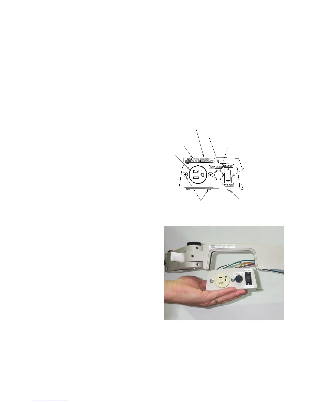
To convert the Slit Lamp Arm to a left-handed unit,
remove the four (4) #8-32 Screws that hold the Cover
Plates with the Outlet and Rocker Switch. Carefully pull
the Plates off of the Upper Arm. Loosen the center Screw
holding the two plates together but do not completely
remove it. Pull the two Plates apart and rotate them so
the Outlet and Rocker Switch are now on the opposite
side of the Upper Arm.
Be careful not to pinch any wires between the Plates and
the Upper Arm when making this change.
2.9.1.2 Loosen the three Set Screws that lock the Arm
Extension in place at the end of the Slit Lamp Arm. Loosen
the Black Knob on top of the Slit Lamp Arm. Rotate Arm
Extension so it is approximately 60 degrees from the side
of the Upper Arm of the Slit Lamp Arm and tighten the Set
Screws. Tighten the Black Knob on top of the Slit Lamp
Arm. Remove Adjustable Handle and Plug Button from the
Arm Extension and place them on the opposite side they
were on. (See Figure 4) and (See Figures 4a, 4b, 4c, 4d
page 10 and Figure 27 page 42 for details.)
OUTLET
PUSH BUTTON SWITCH W/ IR (SHOWN)
ROCKER
#8-32 PHMS
VOLTAGE LABEL
#8-32 THMS
UPPER ARM COVER PLATE
OPPOSITE SIDE
UPPER ARM COVER PLATE, PLAIN
PLUG BUTTON W/O IR
SWITCH
FIGURE 4
FIGURE 4A