IN-790018
Well #3
• Controls room light(s) when the rechargeable instrument
is removed from the well.
• When the instrument is returned to the well, the room lights
return to Scene #1. See section 3.8.3 for Programming
Instructions.
• See Switch 4 on Switchpack #1.
• On a low voltage 520, 522, 6200 or FXM920 Chair,
this switch causes the Chair Base to lower to its lowest
position.
CAUTION- The chair will continue to move
after this switch is released. To STOP chair
movement, press this switch a second time
or press the STOP switch located on the side
of the chair back.
PRÉCAUTION : La chaise continue de se
déplacer après que cet interrupteur est
relâché. Pour ARRÊTER le mouvement de
la chaise, appuyez sur cet interrupteur une
deuxième fois ou appuyez sur l’interrupteur
STOP (ARRÊT) situé sur le côté du dossier
de la chaise.
3.7. Fuses
WARNING: DISCONNECT EQUIPMENT
FROM MAIN INPUT POWER BEFORE PRO-
CEEDING WITH ELECTRICAL INSPECTIONS
OR MAINTENANCE.
AVERTISSEMENT : DÉCONNECTEZ
L’ÉQUIPEMENT DE L’ALIMENTATION
ÉLECTRIQUE PRINCIPALE AVANT
DE PROCÉDER À DES INSPECTIONS
ÉLECTRIQUES OU À DE L’ENTRETIEN.
CAUTION: Replace fuse(s) as marked. All
fuses must be replaced with a fuse of the
same size and rating. Refer to the Wire
Diagrams at the end of this Manual.
PRÉCAUTION : Remplacez le(s) fusible(s)
comme indiqué. Tous les fusibles doivent
être remplacés par un fusible de la même
dimension et de la même valeur. Se référer
aux schémas de câblage à la fin de ce
manuel.
3.7.1.
Floor Units contain two fuses located inside the AC
Input Module on the Outlet Plate Assembly.
3.7.2.
Console and Base Cap contain no additional fuses.
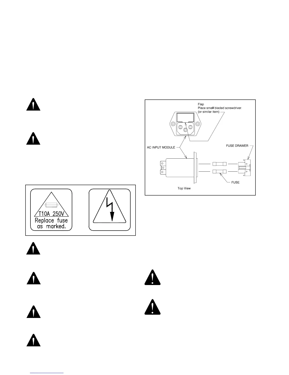
3.7.3. Fuse Replacement (AC Input Module)
Unplug the power cord from the Floor Unit. With a tool
similar to a small common screwdriver, unsnap the locking
tab on the bottom of the
Fuse Drawer
. Remove and
examine the fuses. Replace as necessary. See Figure 9.
Method for removing Fuse Drawer:
1. The Fuse Drawer is located above the power cord.
2. Remove the Power Cord.
3. Place a small bladed screwdriver behind ap and pry
out. The Fuse Drawer will come forward slightly.
CAUTION: To avoid a bind of the Fuse
Drawer within the AC Input Module, never
install the Fuse Drawer into the AC Input
Module without fuses.
PRÉCAUTION : Pour éviter que le tiroir à
fusible reste bloqué dans le module d’entrée
CA, n’installez jamais le tiroir à fusible
à l’intérieur du module d’entrée CA sans
fusibles.
FIGURE 11