IN-7900
9
2.3. Support Column Installation
Remove Phillips Head Shipping Screw. Unwrap the Support
Column. Remove the column Support Pin and the Collar
from the Installation Packet. Insert the Column in the hole
at the top of the Base Unit.
CAUTION – Ensure there is a clear path for
the support column between the opening in
the console and the hole in the base frame.
If cables impede path simply move them
aside.
PRÉCAUTION : Assurez-vous qu’il y a un
passage dégagé pour la colonne de soutien
entre l’ouverture dans la console et le trou
dans le cadre de la base. si des câbles
nuisent, poussez-les simplement de côté.
Line up the hole in the Column with the hole in the Base
Unit and insert the Support Pin. Note that the small screw
at the top of the Column faces the rear of the Base Unit.
Tighten the set screws under the Support Pin. Remove set
screw from Installation Packet and install where shipping
screw had been. Slide the Collar down rmly against the
Console/Base Cap. Insert and tighten set screw.
2.4. CONFIGURING THE SYSTEM
CAUTION – If the Dip Switches are not
configured properly before turning on power
to the equipment via the STBY Switch,
damage to the equipment or Instrument
Bulbs may occur.
PRÉCAUTION : Si les commutateurs dip
ne sont pas configurés correctement avant
d’activer l’alimentation à l’équipement
par l’interrupteur STBY (EN ATTENTE), un
dommage à l’équipement ou aux bulbes
d’instrument peut se produire.
2.4.1. CONSOLE: CONFIGURING DIP SWITCHES ON
THE CIRCUIT BOARD (SW2)
2.4.1.1. Switchpack SW2 on the Console must be
congured for proper operation of the Stand. Individual
switches 1, 2 and 3 control the voltage and power to the
Indirect Ophthalmoscope. See Table 1.
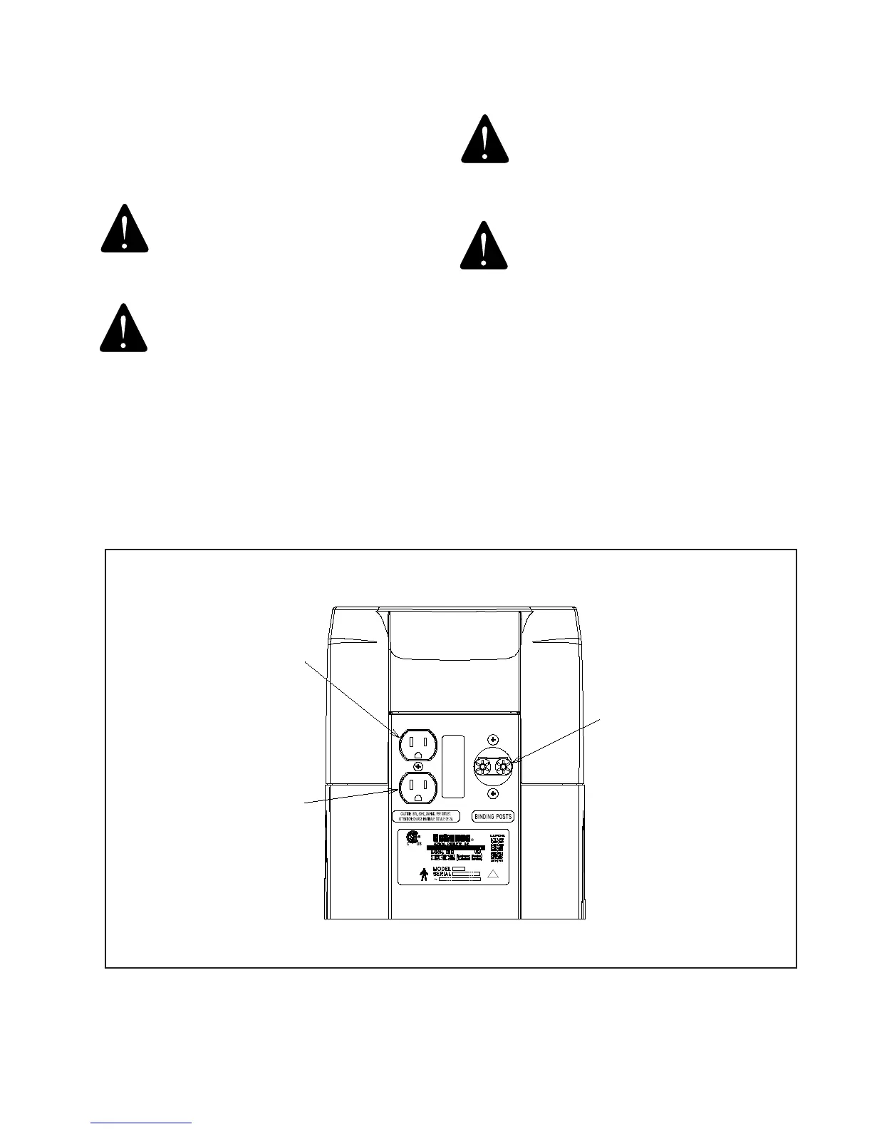
BINDING
POSTS
"3rd" ARM
PROJECTOR
!
FIGURE 3