IN-79008
NOTE:
If you are installing room light controls on
this Instrument Stand, also refer to the “ECLIPSE®
Room Light Control Operating Instructions
Section.”
REMARQUE: Si vous installez des
commandes d’éclairage salle sur ce
stand instrument, se reporter également
à la “ECLIPSE ® light salle de contrôle
d’exploitation des instructions de l’article.”
2.2.1. Replacement or Repair
In the event that the Instrument Console or Base Cap must
be mounted or removed for replacement or repair purposes,
it will be necessary to temporarily remove any assemblies
on the Support Column. To install a Console, connect the
four connectors on top of the Base Unit to the matching
connectors hanging from the bottom of the Console.
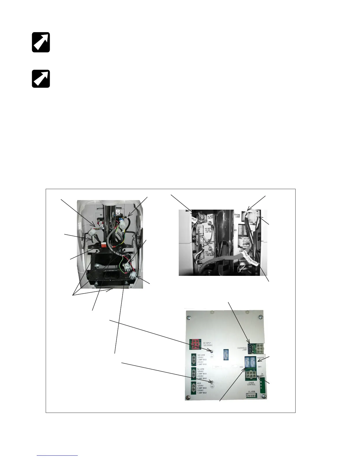
FIGURE 2
The Lamp Jumper Cable will drop through the large opening
and be connected to the matching connector that hangs
from underneath the Support Column. Figure 2 illustrates
the connections that must be made. Align the two pins
located near the front of the Console in the matching holes
on top of the Base Unit. Gently push the Console down to
secure.
To disassemble or remove the Console, pull the Console
up in the front and disconnect the four connectors from the
Base Unit. As mentioned above, any assemblies on Support
Column must be removed before the Console itself can
be removed. If the Overhead Lamp has not already been
removed, the Lamp Jumper must be disconnected from
the lamp plug under the Support Column.
Chair Control (Ref)
Overhead Lamp
Slit Lamp Arm
from Roller
Frame
AC Input from
Outlet Plate
3rd Arm from
Back Cover
Aux from Back
Cover
Overhead Lamp
Jumper
B/P Jumper
from Module
Chair Control
from Outlet
Plate
Ground from AC
Input
Ground from 3rd Arm & Slit
Lamp
Overhead
Lamp
Switchpack
(SW1)
Optional
Chair
Control
Switchpack
(SW2)
Mounting Tabs
FIGURE 2