IN-7900
13
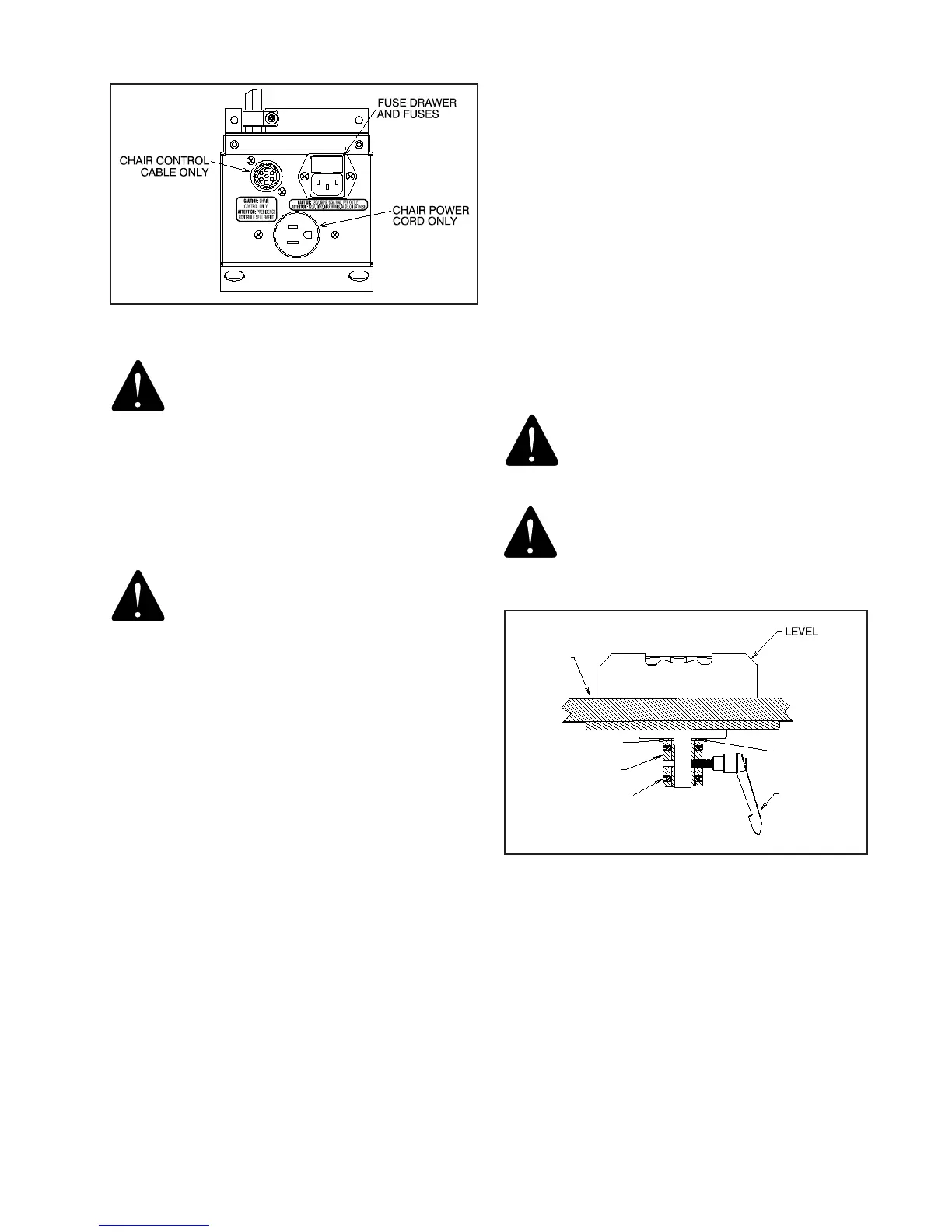
FIGURE 5
WARNING- THE MAINS OUTLET LOCATED
ON THE OUTLET PLATE ASSEMBLY IS
INTENDED TO SUPPLY POWER TO A RELI-
ANCE® PATIENT EXAMINATION CHAIR OR
SIMILAR MEDICAL DEVICE COMPLYING
WITH IEC 60601-1. ONCE CONNECTED,
RESULTING LEAKAGE CURRENTS MUST
COMPLY WITH IEC 60601-1-1 FOR MEDI-
CAL ELECTRICAL (ME) SYSTEMS. DO NOT
CONNECT UNAUTHORIZED DEVICES.”
AVERTISSEMENT : LA PRISE DE COURANT
SITUÉE SUR L’ASSEMBLAGE DE PLAQUE
DE COURANT EST CONÇUE POUR FOURNIR
L’ALIMENTATION À UNE CHAISE D’EXAMEN
DE PATIENT RELIANCE® OU À UN DISPOSITIF
MÉDICAL SIMILAIRE CONFORME À IEC
60601-1. UNE FOIS L’APPAREIL CONNECTÉ,
LES COURANTS DE FUITE RÉSULTANTS
DOIVENT ÊTRE CONFORMES À IEC 60601-
1-1 POUR LES SYSTÈMES ÉLECTRIQUES
MÉDICAUX. NE CONNECTEZ PAS DE
DISPOSITIFS NON AUTORISÉS.
2.11. Miscellaneous
2.11.1. When attaching an instrument to the Slit Lamp Arm,
note the Thrust Bearing which should be in place between
the instrument and the arm. See Figure 4.
2.11.2. Proper balance of an Instrument on the Slit Lamp
Arm is achieved by adding or removing counter-balance
weights as shown in Figure 5. See Table 2 for weight
settings.
2.11.3. Finally, plug the power cord into a wall receptacle
and check all electrical functions as described in the
Operating Instructions. If all functions are normal, attach
the Base Unit Rear Cover.
2.11.4. To disconnect power from the Instrument Stand,
unplug power cord from wall receptacle.
3. OPERATING INSTRUCTIONS
3.1. Slit Lamp Arm
3.1.1. The Slit Lamp Arm is counterbalanced by means
of weights and all its movements are controlled manually.
3.1.2. The vertical lock for this arm is controlled by the
Lock Release Lever
located under the Slit Lamp Arm. (See
Figure 1). Grip the Slit Lamp Arm and depress the
Lock
Release Lever
to unlock the Slit Lamp Arm. Releasing
the
Lock Release Lever
will lock vertical travel in both
directions.
WARNING: SLIT LAMP ARM WILL RISE
ABRUPTLY IF RELEASE LEVER IS DE-
PRESSED AND ARM IS NOT COUNTER-
BALANCED.
AVERTISSEMENT : LE BRAS DE LA LAMPE
À FENTE SE LÈVERA ABRUPTEMENT SI LE
LEVIER DE DÉGAGEMENT EST PRESSÉ ET
QUE LE BRAS N’EST PAS CONTREBALANCÉ.
3.1.3. Incremental weights are added or removed to
achieve proper balance in accordance with the Weight
Settings-Slit Lamp Arm chart. (See also Figure 5).
3.1.4. The knob under the innermost pivot point of the Slit
Lamp Arm (Figure 1) is to restrain rotation of the complete
arm assembly. The knob at the intermediate joint on the Slit
Lamp Arm locks rotation of the outer arm section. The knob
directly under the Slit Lamp locks rotation of the Instrument
about its pivot point.
LEVELING
SLEEVE
OUTERMOST
HANDLE
SET SCREWS
(6)
BEARINGS
OUTER ARM
SLIT LAMP
TABLE
FIGURE 6