IN-790014
3.1.6. The outermost Handle can be adjusted to any
preferred, locked position. Simply pull out on handle, rotate
as desired, and release.
3.1.7. The Outer Arm contains an outlet for Instrument
power, and a Rocker Switch to control vertical movement
of the chair. The Chair Control Cable (Item 17, Figure 20)
must be installed. (Refer to Section 2.9). Depress the “UP”
arrow on the switch to raise the chair. Depress the “Down”
arrow to lower the chair.
WARNING- THE MAINS OUTLET LOCATED
ON THE SLIT LAMP ARM IS INTENDED TO
SUPPLY POWER TO A SLIT LAMP COMPLYING
WITH IEC 60601-1. ONCE CONNECTED,
RESULTING LEAKAGE CURRENTS MUST
COMPLY WITH IEC 60601-1-1 FOR MEDICAL
ELECTRICAL (ME) SYSTEMS. DO NOT
CONNECT UNAUTHORIZED DEVICES.
AVERTISSEMENT : LA PRISE DE COURANT
SITUÉE SUR LE BRAS DE LA LAMPE À
FENTE EST CONÇUE POUR FOURNIR
L’ALIMENTATION À UNE LAMPE À FENTE
CONFORME À IEC 60601-1. UNE FOIS
L’APPAREIL CONNECTÉ, LES COURANTS
DE FUITE RÉSULTANTS DOIVENT ÊTRE
CONFORMES À IEC 60601-1-1 POUR LES
SYSTÈMES ÉLECTRIQUES MÉDICAUX. NE
CONNECTEZ PAS DE DISPOSITIFS NON
AUTORISÉS.
NOTE: Switch action is momentary; but may
be programmed to function as maintained
depending on the chair model. See chair manual
for programming instructions.
REMARQUE : L’action de l’interrupteur est «
momentané », mais peut être programmé pour
fonctionner comme « maintenu » selon le modèle
de chaise. Consultez le manuel de chaise pour les
instructions de programmation.
3.2. Third Arm
3.2.1. Three knobs control all motions of this Arm
Assembly. The one nearest the Column controls rotation
about the Support Column. The lever at the pivot point of the
Outer Arm controls both vertical movement and the rotation
of the Outer Arm. The small knob in the Outer Arm controls
rotation of the Instrument at the outermost pivot point.
3.2.2. Adjustment of the Spring counterbalance is as
described in the Installation Instructions, Section 2.5.3.
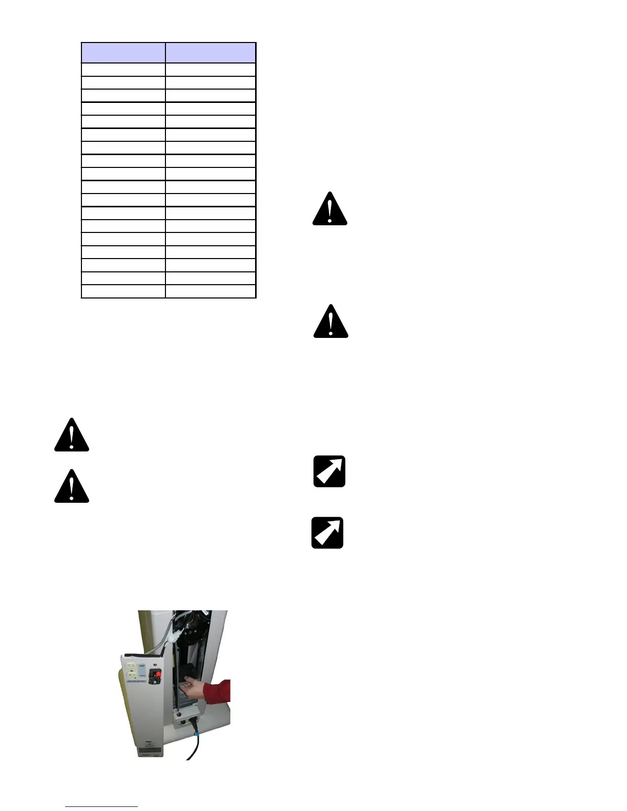
INSTRUMENT GROSS
WEI GHT-lbs.(kg )
INCREMENTAL WEIGHTS
12-16 ( 5.44-7.25) None
16-20 ( 7.25-9.0) Light
20-23 ( 9.0-10.43) Medium
23-25 ( 10.43-11.34) Heavy
25-28 ( 11.34-12.7) Light, Medium
28-30 ( 12.7-13.6) Light, Heavy
30-33 ( 13.6-14.97) Medium, Heavy
33-35 ( 14.97-15.88) 2 Heavy
35-38 ( 15.88-17.24) Light, Medium, Heavy
38-40 ( 17.24-18.14) 1 Light, 2 Heavy
40-43 ( 18.14-19.5) 1 Medium, 2 Heavy
43-45 ( 19.5-20.41) 3 Heavy
45-48 ( 20.41-21.77) 1 Light, 1 Medium, 2 Heavy
48-50 ( 21.77-22.68) 1 Light, 3 Heavy
50-53 ( 22.68-24.04) 1 Medium, 3 Heavy
53-55 ( 24.04-24.95) 4 Heavy
55-58 ( 24.95-26.31) 1 Light, 1 Medium, 3 Heavy
58-60 ( 26.31-27.22) 1 Light, 4 Heavy
Table 2
Weight Settings-Slip Lamp Arm Chart
3.1.5. The outer end of the Slit Lamp Arm contains a
Leveling Sleeve and six set screws for eld re-leveling of
the Instrument, if necessary. A hex key wrench (1/8) and a
small, accurate level will be required. Remove the Instrument
from the table and refer to Figure 4.
WARNING- WITH INSTRUMENT REMOVED,
ARM WILL RISE ABRUPTLY IF RELEASE
LEVER IS DEPRESSED.
AVERTISSEMENT : L’INSTRUMENT ÉTANT
RETIRÉ, LE BRAS DE LA LAMPE À FENTE SE
LÈVERA ABRUPTEMENT SI LE LEVIER DE
DÉGAGEMENT EST PRESSÉ.
The outermost Handle must be threaded into the Leveling
Sleeve, but not tightened. Rotate the Slit Lamp Arm to the
examining position and tighten the other (2) handles. It may
be necessary to loosen several set screws to reposition
screws securely and check level again.
FIGURE 7