REM - GRAINVAC VR12 5. MAINTENANCE
5.4. MAINTENANCE PROCEDURES
9000-00-0042 R3 59
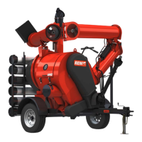
Figure 5.10 Angular & Horizontal Adjustment Bolts
2. If the belt is misaligned, first make the coarse or angular adjustment (see Figure
5.10). This is achieved by slightly loosening the 4 x 1/2” angular adjustment bolts
that secure the shaft mount to the pedestal, and then by adjusting the two horizontal
adjustment bolts to rotate the shaft mount. These bolts must be adjusted equally (in
other words,1 turn in on the top bolt requires 1 turn out on the bottom bolt to
maintain proper position of the idler). The pulley should be adjusted to be parallel to
the belt edge on the tight side of the belt. Then retighten the 4 x 1/2” bolts.
• If the belt remains misaligned in the same direction, then complete the fine pulley
plane adjustment described in Step 3.
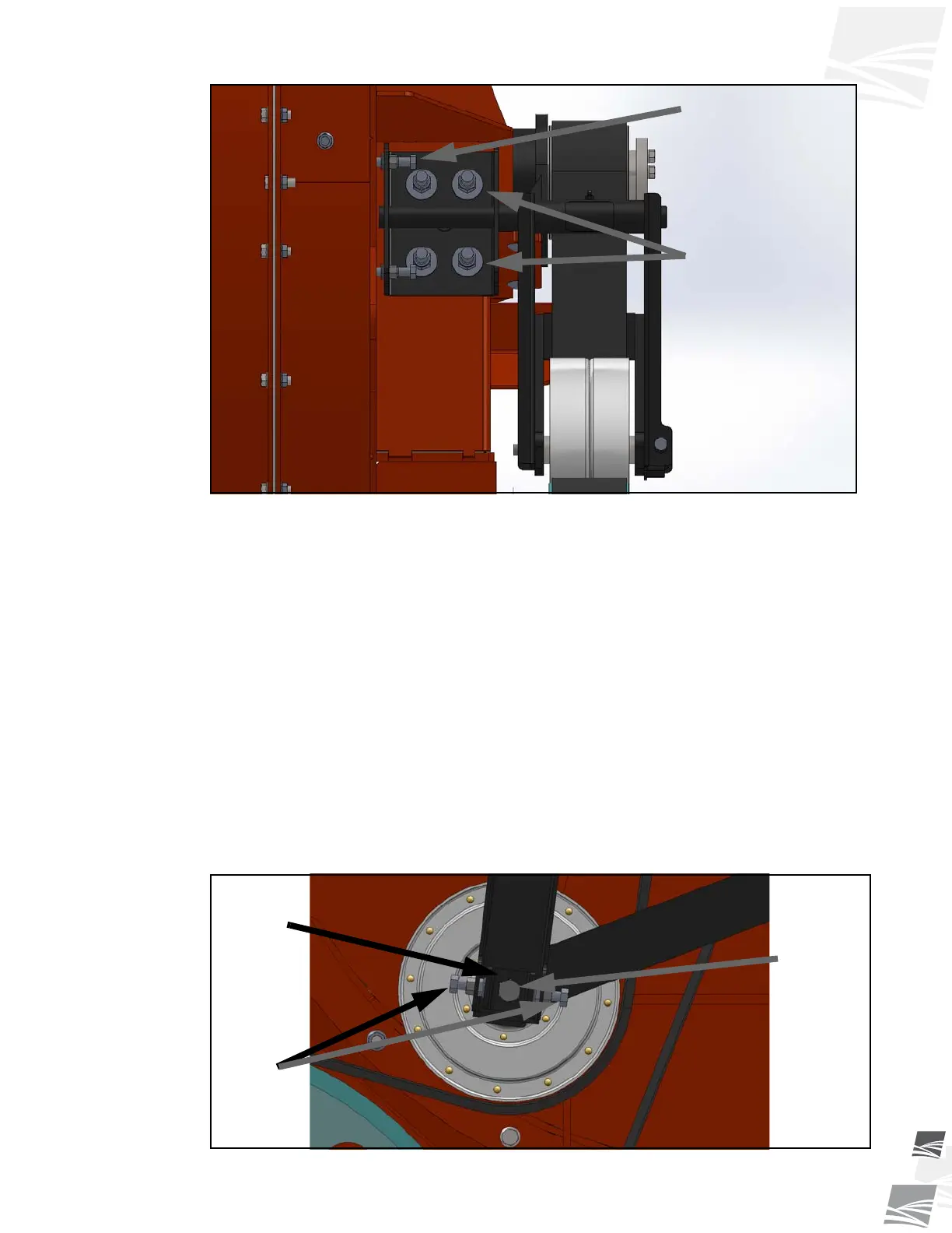
3. Fine (or pulley plane) adjustment of the idler pulley is achieved by first loosening the
1/2” idler axle bolt (see Figure 5.11). Next loosen the 2 x 3/8” jam nuts on the outside
of the box-shaped idler arm, and then using the 3/8” pulley plane adjustment bolts
against the pusher block, to adjust the pulley in the desired direction.
4. Following alignment, retighten all fasteners, and rotate the assembly in the normal
direction of travel to ensure the belt, where it passes over the idler pulley, is not
visible to either side of the belt on the tight side.
Figure 5.11 Pulley Plane Adjustment
HORIZONTAL
ADJUSTMENT BOLTS
ANGULAR ADJUSTMENT
BOLTS
PUSHER
BLOCK
PULLEY
PLANE
ADJUSTMENT
BOLTS
IDLER AXLE
BOLT