22
en
2.2 Electrical connection
WARNING!
Electric shock!
Upon opening the housing, live parts are exposed!
Î Always disconnect the controller from power supply
before opening the housing!
ATTENTION!
ESD damage!
Electrostatic discharge can lead to damage to electronic com-
ponents!
Î Take care to discharge properly before touching the
inside of the device!
Note
Connecting the device to the power supply must always be the last step
of the installation!
Do not use the device if it is visibly damaged!
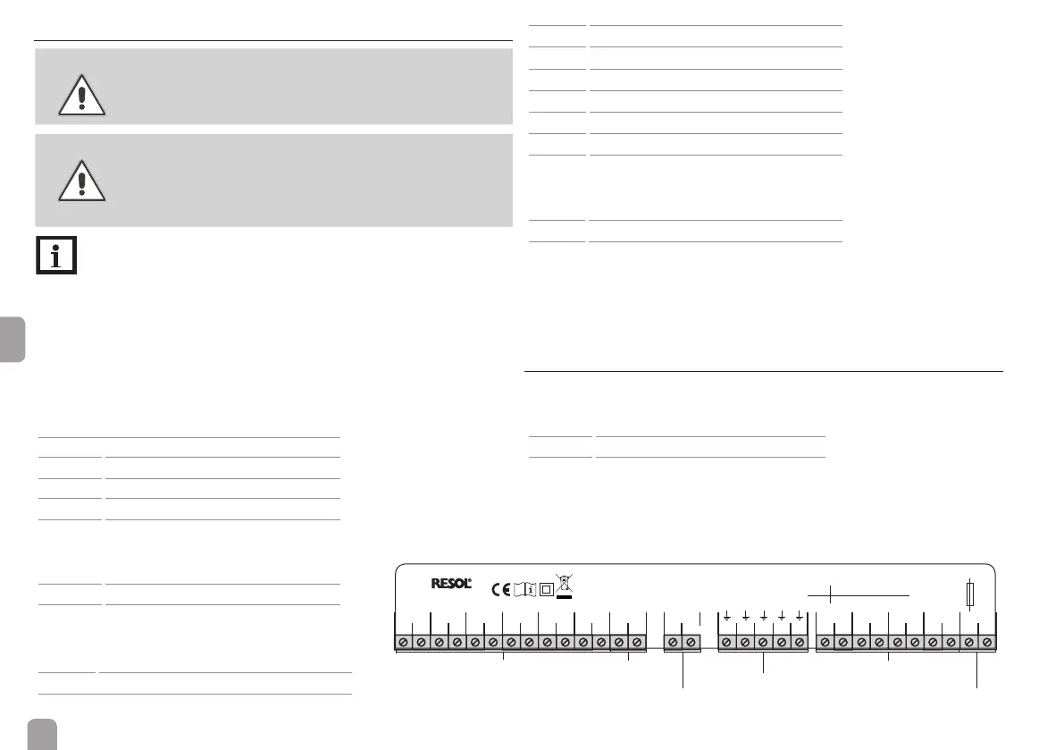
The device is equipped with 4 semiconductor relays and 1 potential-free relay to
which loads such as pumps, valves, etc. can be connected.
Depending on the product version, the mains cable and the sensor cables are already
connected to the device. If that is not the case, please proceed as follows:
Connect the temperature sensors (S1 to S6) to the corresponding terminals
with either polarity:
1/2
sensor 1 (e.g. ow HC2)
3/4 sensor 2
5/6 sensor 3
7/8 sensor 4
9/10 sensor 5
11/12 sensor 6
Potential-free relay:
15 conductor R5-A (normally open contact)
16 conductor R5-M (normally closed contact)
17 … 21
ground terminal ⌯
Semiconductor relays:
22
neutral conductor R4
23
normally open contact R4
24
neutral conductor R3 (e.g. mixer closed HC2)
25
normally open contact R3 (e.g. mixer closed HC2)
26
neutral conductor R2 (e.g. mixer open HC2)
27
normally open contact R2 (e.g. mixer open HC2)
28
neutral conductor R1 (e.g. pump HC2)
29
normally open contact R1 (e.g. pump HC2)
17 … 21
ground terminal ⌯
Connect the mains cable to the following terminals:
30
neutral conductor N
31
conductor L
17 … 21
ground terminal ⌯
Attach exible cables to the housing with the enclosed strain relief and the cor-
responding screws.
The device is supplied with power via the mains cable. The mains voltage must be
100 … 240 V~ (50 … 60 Hz).
2.3 Data communication / Bus
The device is equipped with a RESOL VBus
®
for data communication with the
controller. Carry out the connection at the two terminals marked VBus (any
polarity).
13/14 VBus terminals
The VBus
®
cable can be extended or replaced with a two-wire cable (bell wire; the
cross section must be at least 0.5 mm²). The cable can be extended to up to 50 m in the
case that one module is used. The distance can be increased by using a VBus
®
-Repeater.
sensor terminals
ground common
terminal block
load terminals
mains terminals
VBus
®
S1
Made in Germany
EM
IP 20
12345678910 11 12 13 14 15 17 18 19 20 21 22
R1-R4 1 (1) A (100 ... 240) V~
4 (1) A (100 ... 240) V~
100 ... 240 V~
50-60 Hz
T4A
R5
NNNNNLR1R2R3R4
23 24 25 26 27 28 29 30 31
R5-A
R5-M
16
S2 S3 S4 S5 S6 VBus
potential-free relay
 Loading...