28
en
5 Menu system
5.1 Channel overview
Channel Description Page
S1 D Value at sensor 1
29
S2 D Value at sensor 2
29
S3 D Value at sensor 3
29
S4 D Value at sensor 4
29
S5 D Value at sensor 5
29
S6 D Value at sensor 6
29
R1 D Speed relay 1
29
R2 D Speed relay 2
29
R3 D Speed relay 3
29
R4 D Speed relay 4
29
R5 D Status relay 5*
29
VC D Version compatibility
29
EC D Error code
29
M1 P Manual mode R1
29
M2 P Manual mode R2
29
M3 P Manual mode R3
29
M4 P Manual mode R4
29
M5 P Manual mode R5
29
MM P Slide switch manual mode
29
T1 P Sensor type sensor 1
29
T2 P Sensor type sensor 2
29
T3 P Sensor type sensor 3
29
T4 P Sensor type sensor 4
29
T5 P Sensor type sensor 5
29
T6 P Sensor type sensor 6
29
SA P Sub-address
30
PG D Program
29
VN D Version number
29
Legend:
Symbol Specication
D Display channel
P Adjustment parameter
* R5 is a potential-free relay not suitable for speed control. Therefore, its status is indicated
with 0 % or 100 % respectively.
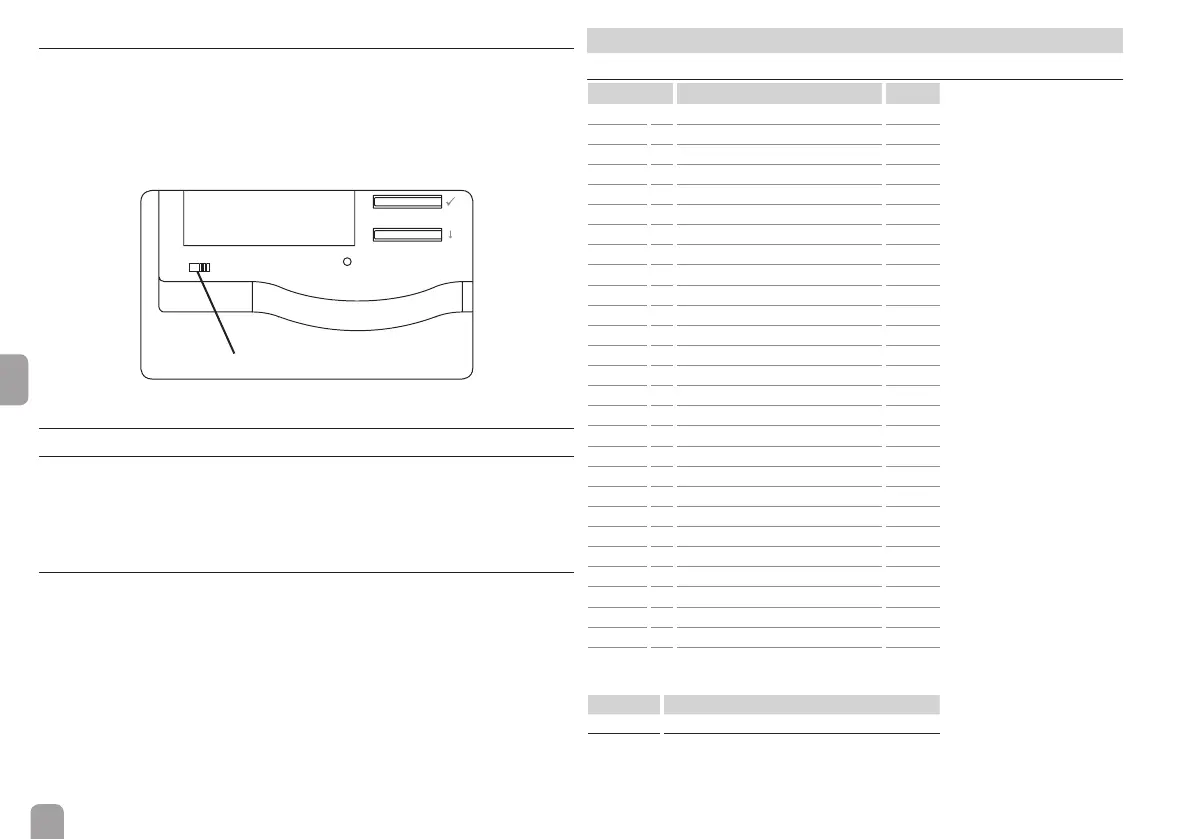
4.3 Slide switch
By means of the slide switch, an adjustable selection of relays (see channel MM,
page 29) can be switched on (I) or off (0) manually. When the slide switch is set
to Auto, the adjustments of the channels M1 … M5 are valid.
Manually OFF = 0 (left)
Manually On = I (right)
Automatic mode = Auto (mid position) – adjustments made in M1 … M5
Slide switch
4.4 Flashing codes and warning symbols
4.4.1 LED ashing codes
green: everything OK
green ashing: manual mode
red ashing: VBus
®
cable broken or controller not detected
4.4.2 Warning symbols
⚠ = no VBus
®
communication
☛ = manual mode (see chap. 4.3):
ashing: slide switch in position I
permanent: slide switch in position 0