23
en
mains terminals
3 Initial commissioning
DeltaTherm
®
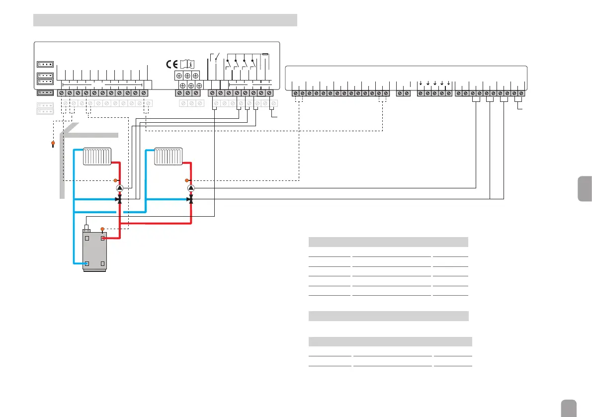
HC with scheme 2: 1 mixed heating circuit with backup heating
S1
12345678910 11 12 13 14 15 17 18 19 20 21 22
NNNNNLR1R2R3R4
23 24 25 26 27 28 29 30 31
R5-A
R5-M
16
S2 S3 S4 S5 S6
VBus
S2
S1
M1-S1
R1
R2/3
M1-R3
S1
S2
S3
S4
S5
S6
S7
S8
R4
R5
IP20
R5
N
R3
R2
R1
L' L
GND
RPD
VFD
CS10
V40/S9
VBus
VBus
GND
S4
R5
M1-R1/2
Mains
Mains
19/N/PE
0-10V/PWM
A B
EM as module 1 for mixed heating circuit 2
The EM is an extension module which can be connected to a DeltaSol
®
MX,
DeltaTherm
®
HC or DeltaSol
®
BX Plus controller.
All adjustments for the extension module menu are to be carried out on the controller.
In the following, the step-by-step adjustment in combination with the Delta-
Therm
®
HC controller is described.
In this example, the extension module is used for controlling a second heating
circuit. The outdoor temperature sensor (S2) and the optional backup heating de-
mand (R5) of the DeltaTherm
®
HC are available for both heating circuits.
For initial commissioning, proceed as follows:
Î Connect the EM to the controller by means of the VBus
®
cable.
Î Connect the ow sensor, pump and mixer of the second heating circuit to the
extension module (see table).
Sensors
M1-S1 Flow HK2 1 / 2
M1-S2 free 3 / 4
M1-S3 free 5 / 6
M1-S4 free 7 / 8
M1-S5 free 9 / 10
M1-S6 free 11 / 12
Data communication / Bus
M1-VBus VBus
®
13 / 14
Relays
M1-R1 Pump HC2 29 / 28 / PE
M1-R2 Mixer open HC2 27 / 26 / PE
M1-R3 Mixer closed HC2 25 / 24 / PE
Î Establish the power supply.