Slide the rotor onto the motor shaft up to the stop.
NOTICE If it is hard to slide the rotor or if it cannot be pushed up to the stop, check the correct
and firm fit of the feather key (PF) on the motor shaft (MW). In addition, the motor shaft can be
oiled with some machine oil.
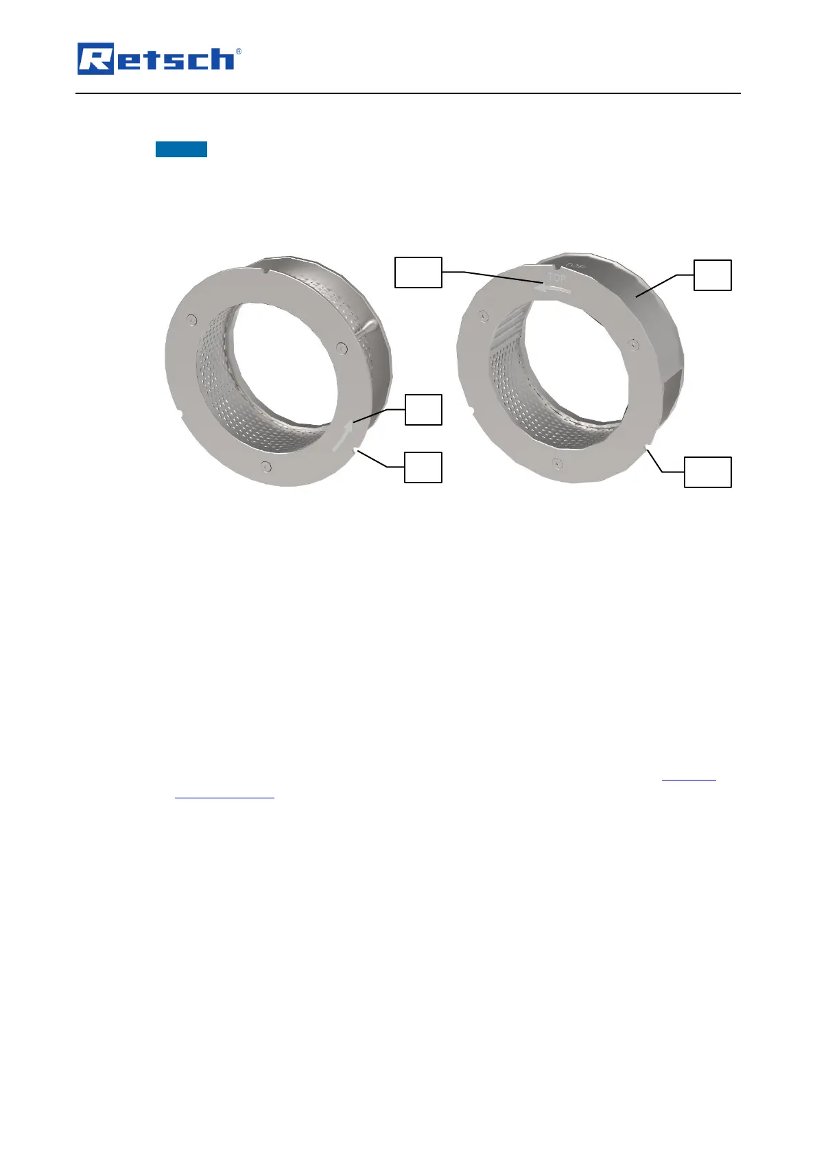
6.7.3 Inserting the Retaining Frame
Both, the retaining frame for the 360° sieve inserts and the 180° sieve inserts have a direction
arrow (SR1) or (SRM1) on the front, which indicates the direction of rotation of the rotor
(counterclockwise).
Pull up and hold the locking pin (E).
Align the retaining frame so that the direction arrow (SR1) or (SRM1) is facing forward and
the three recesses (SR2), (SRM2) are aligned with the corresponding cylinder pins. In the
case of the retaining frame for the 180° sieve inserts, "TOP" must additionally be on top.
Slide the retaining frame into the grinding chamber cartridge (MK).
Release the locking pin (E).
Changing the sieve insert:
All available 360° and 180° sieve inserts can be replaced as desired in the corresponding
retaining frames.
Remove the front of the corresponding retaining frame as described in Chapter "Cleaning
the Grinding Set".
Remove the existing sieve insert and replace it by the desired sieve insert instead.
Ensure the correct orientation when inserting sieve inserts with trapezoidal perforation!
The direction of the arrow on the sieve insert must correspond to the direction of the arrow
on the retaining frame! Both indicating the direction of rotation of the rotor
(counterclockwise).
Screw the retaining frame back together.