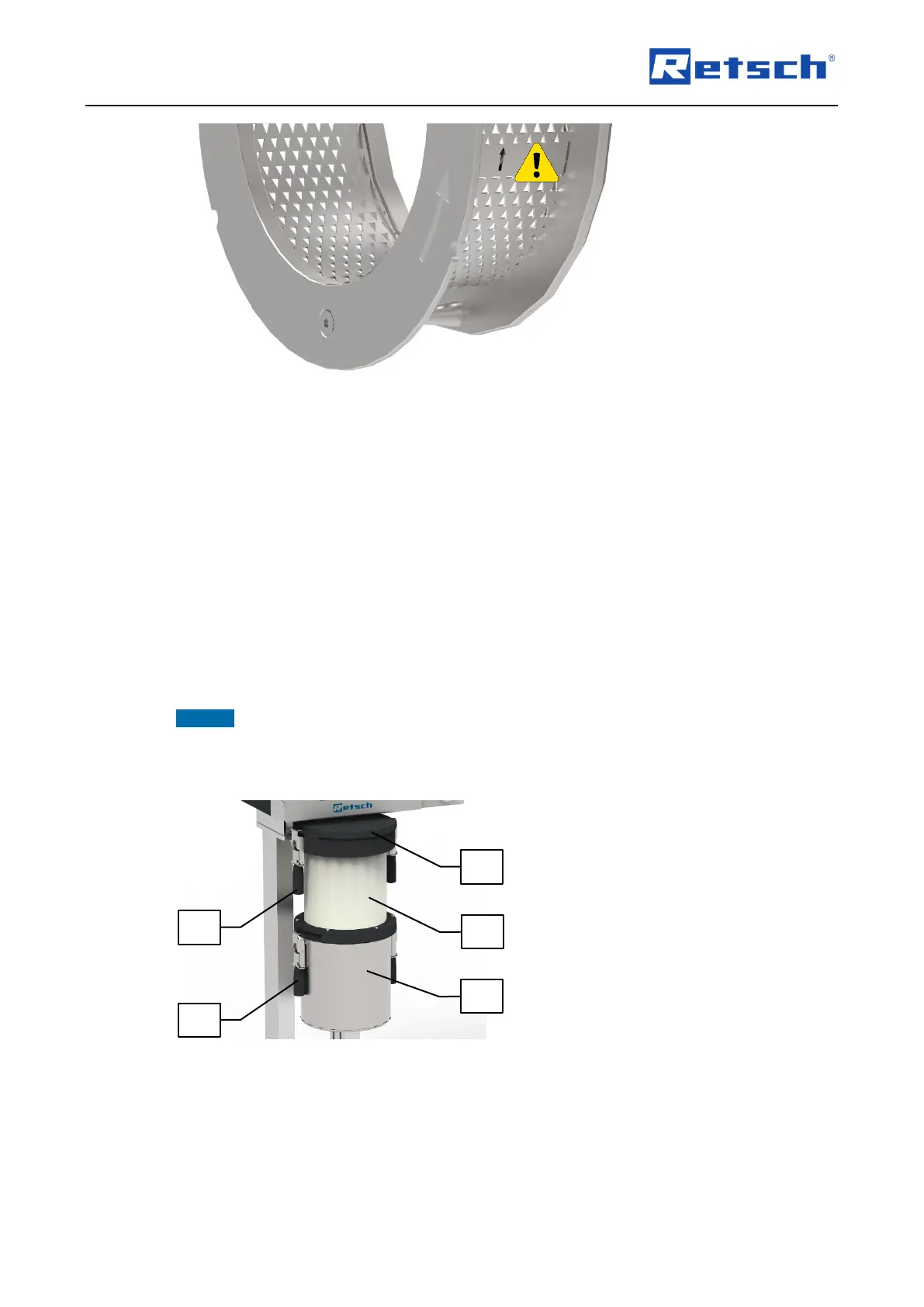
6.8 Removing the Grinding Set
The removal of the grinding set is preferably carried out in the following sequence:
1. Rotor
2. Retaining frame
3. Grinding chamber cartridge
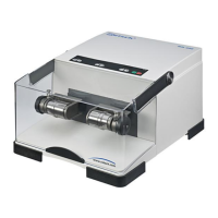
6.9 Mounting the Sample Receptacle
By the use of the textile filter hose (L), or a ring filter that is available as an optional accessory,
attached between the discharge flange (AF) and the collecting receptacle (M), the airflow
generated by the rotating rotor can be dissipated and the material throughput can be
accelerated.
NOTICE If the collecting receptacle is installed without the filter hose or ring filter, it is to be
expected that dust will be emitted out of the feed hopper (F). Therefore, never operate the SR
300 without the filter hose or ring filter!
Use the two horizontally unfolded clamping levers (N) to lift up the filter hose (L).
Position the filter hose (L) flush over the groove (AF1) of the discharge flange.
Turn the filter hose (L) clockwise until the clamping lever is situated over the clamping edge
(AF2).
Press the clamping levers (N) downwards with the open palm to clamp the filter hose (L).