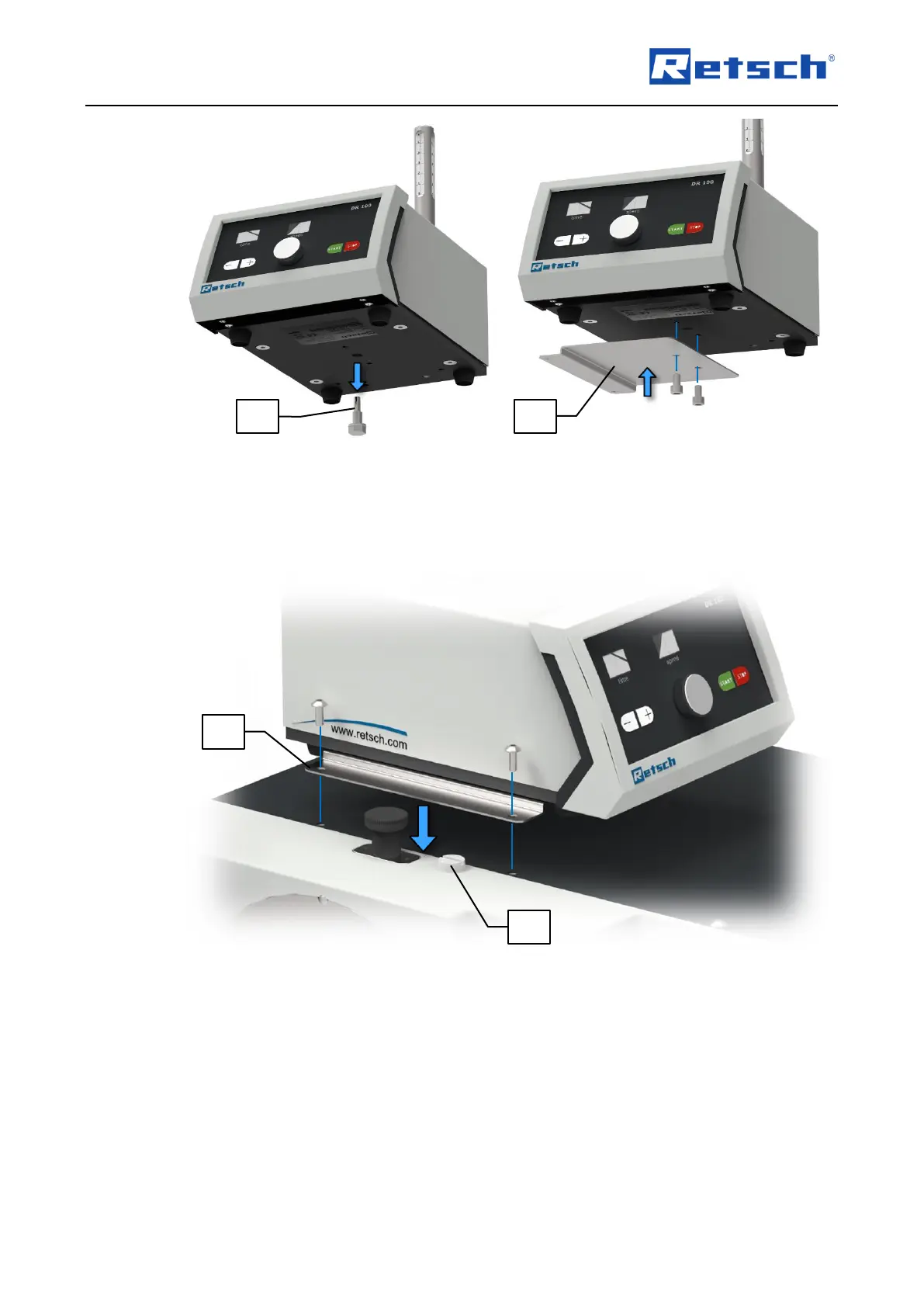
Remove the transportation lock (DR1).
Mount the angle plate (DR2) to the bottom of the DR 100 with the two M6 hexagon socket
head screws supplied, so that it protrudes under the vibratory feeder on the left hand side.
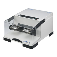
If not already done, replace the transportation lug (A) on the SR 300 with the supplied plastic
screw (PS).
Loosen the two M5 oval-head screws at the housing of the SR 300 and use them to screw
the angle plate (DR2) to the SR 300.
Mount the feed chute holder, the feed chute, the hopper holder and the hopper as described
in the separate manual of the vibratory feeder DR 100.