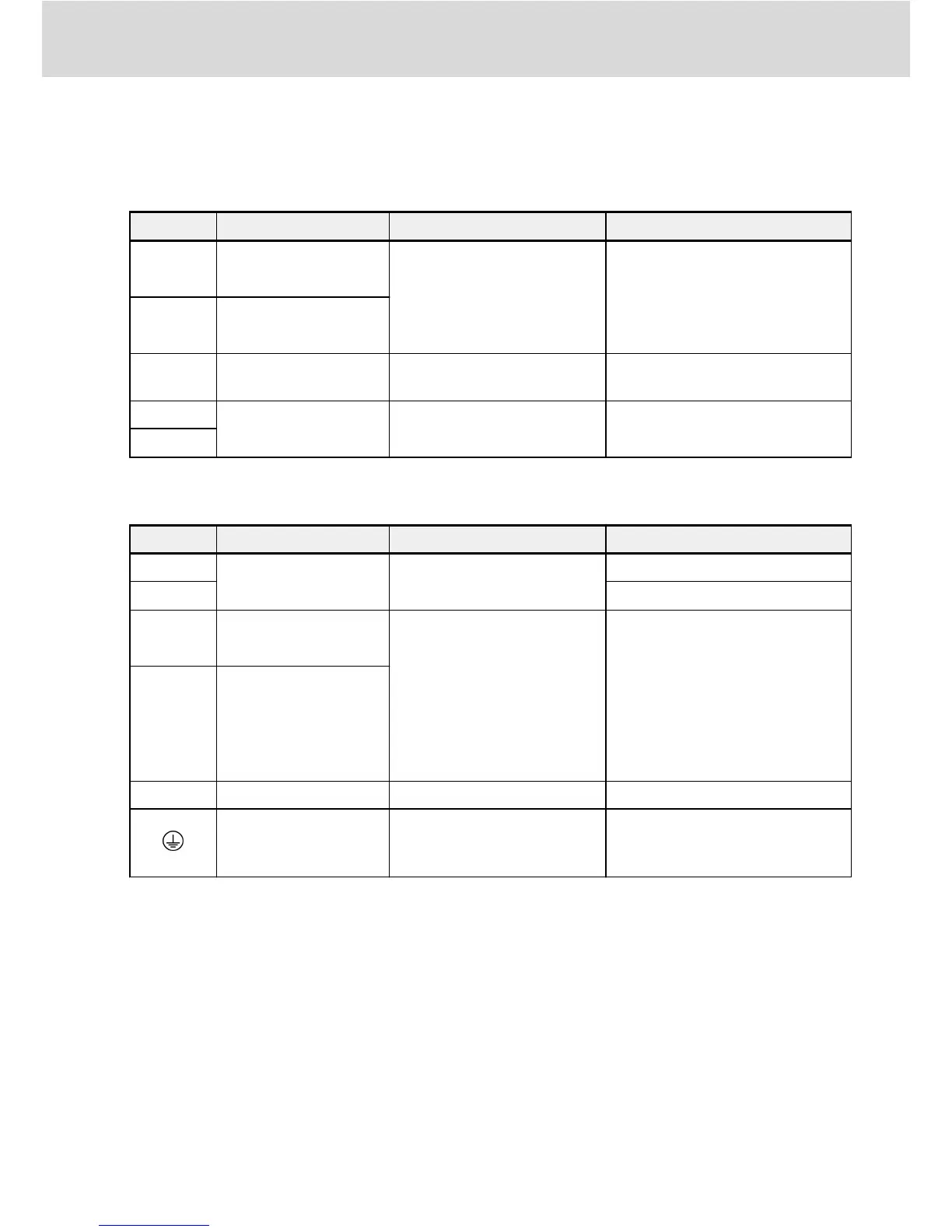
Control terminals description
Digital inputs
Terminal Signal function Description Signal requirement
X1...X5
Multi-function
digital inputs
See Group E1
Inputs via opto-electric couplers:
24 VDC, 8 mA / 12 VDC, 4 mA
Pulse input: Max. 50.0 kHz
X5
(multiplex)
Pulse input
SC Shared connection
Shared connection for isola-
tion opto-electric couplers
–
+24 V Power supply for
digital inputs
COM is reference
Isolated from GND
Max. output current: 100 mA
COM
Analog inputs
Terminal Signal function Description Signal requirement
+10 V Power supply for
analog inputs
GND is reference
Max. output current: 30 mA
+5 V Max. output current: 10 mA
AI1
Analog voltage input 1/
Analog current input 1
Analog voltage / current in-
puts are used as external fre-
quency setting channels
To switch between voltage
and current or to set the input
related functions, see Group
E1
Voltage input range: 0/2...10 V
Input impedance: 27 kΩ
Resolution: 1/1,000
Current input range: 0/4...20 mA
Input impedance: 250 Ω
Resolution: 1/1,000
AI2
Analog voltage input 2/
Analog current input 2
GND Shared connection Isolated from COM –
Shielding connection
Connected with grounding
terminals on heatsink inter-
nally
–
EFC 3610 / EFC 5610 Bosch Rexroth AG
Electric Installation
DOK-RCON03-EFC-X610***-QU11-EN-P
21/87

 Loading...


