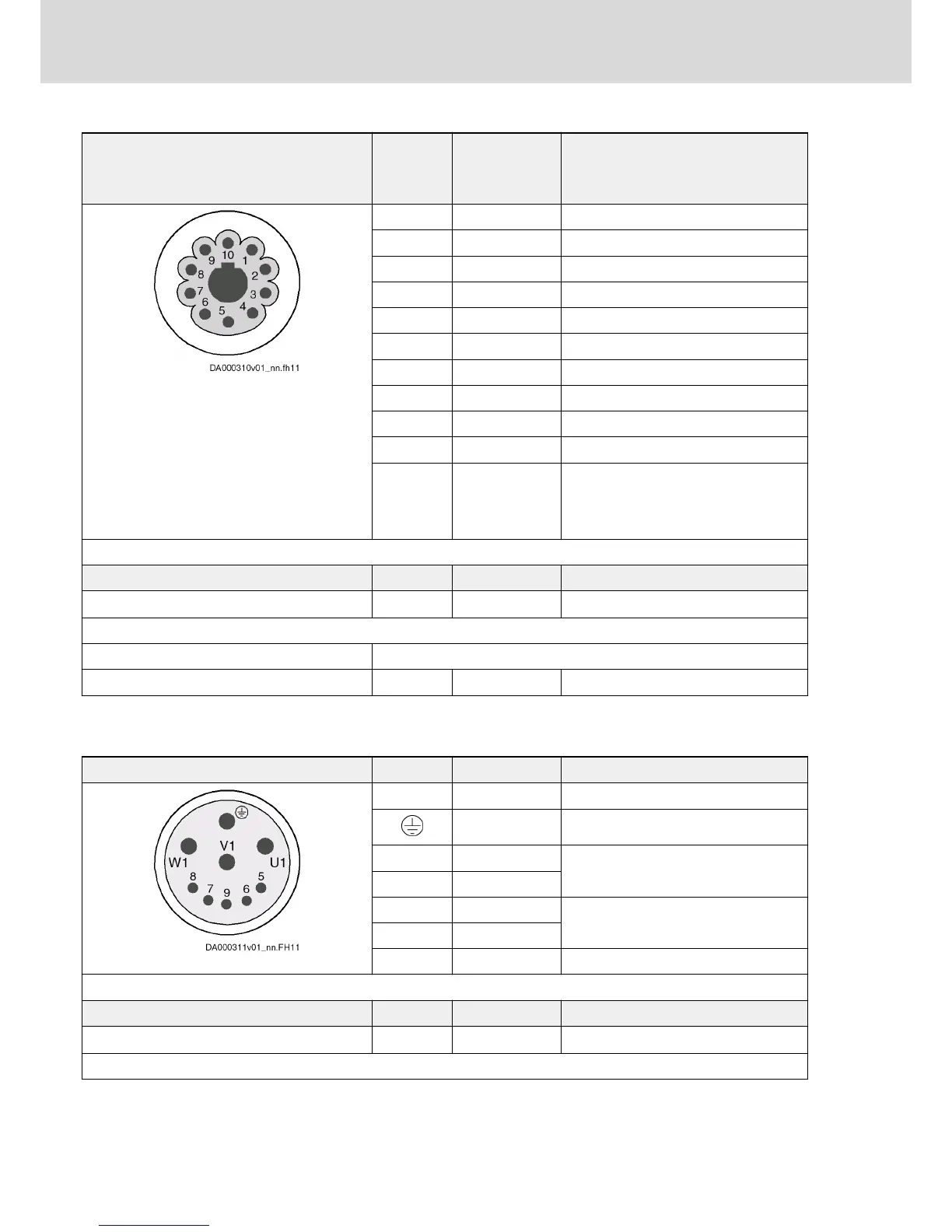
View Connection Signal name
S1, M1
(HIPERFACE®)
Function
1 VCC_Encoder Power supply
2 GND_Encoder Power supply reference potential
3 A + Track A positive
4 A - Track A negative
5 B + Track B positive
6 B - Track B negative
7 EncData+ Data transmission
8 EncData- Data transmission
9 n. c. -
10 n. c. -
Overall
shield via
connector
housing
10-pin, female connector Unit Min. Max.
Connection cable stranded wire
mm
2
n.s. n.s.
Order type of cable RKG4201
Allowed length m n.s. 7,5
Fig.5-2: X104, Motor Encoder
5.2.5 X156, Connection for Motor
View Connection Signal name Function
U1, V1, W1 - Power output
- Equipment grounding conductor
5 MotTemp+ Input temperature measurement (tem‐
perature sensor KTY84)
6 MotTemp-
7 (optional) Br+ / +24V Output for controlling the motor holding
brake
8 (optional) Br- / 0V
9 GND_shld Shield
10-pin, female connector Unit Min. Max.
Connection cable stranded wire
mm
2
n.s. n.s.
Bosch Rexroth AG DOK-INDRV*-KMS01******-IT01-EN-P
Rexroth IndraDrive Mi Distributed Drive Controller KMS01
32/67
Instructions for Use