Setting Description
"00"
S5 = 0
S4 = 0
"00" is the factory setting of the address selector switches.
This setting is not applied. You have to set the individual
drive address in parameter "P-0-4025, Drive address of
master communication", e.g. via the serial interface X2.
The factory setting in P-0-4025 is "01".
"01" … "99"
S5 = 0 … 9
S4 = 0 … 9
Drive address =
S5×10 + S4
Setting of address selector switches is applied to
P-0-4025.
Example for setting drive address "14":
S5 = 1, S4 = 4 ⇒ drive address = 1×10 + 4 = 14
See also documentation Parameter Description:
● "P-0-4025, Drive address of master communication"
● "P-0-4031, Overview of device addresses"
Fig.5-5: Setting the Drive Address at S4 and S5
Order in string of drives
The order of the addresses in a string is without significance.
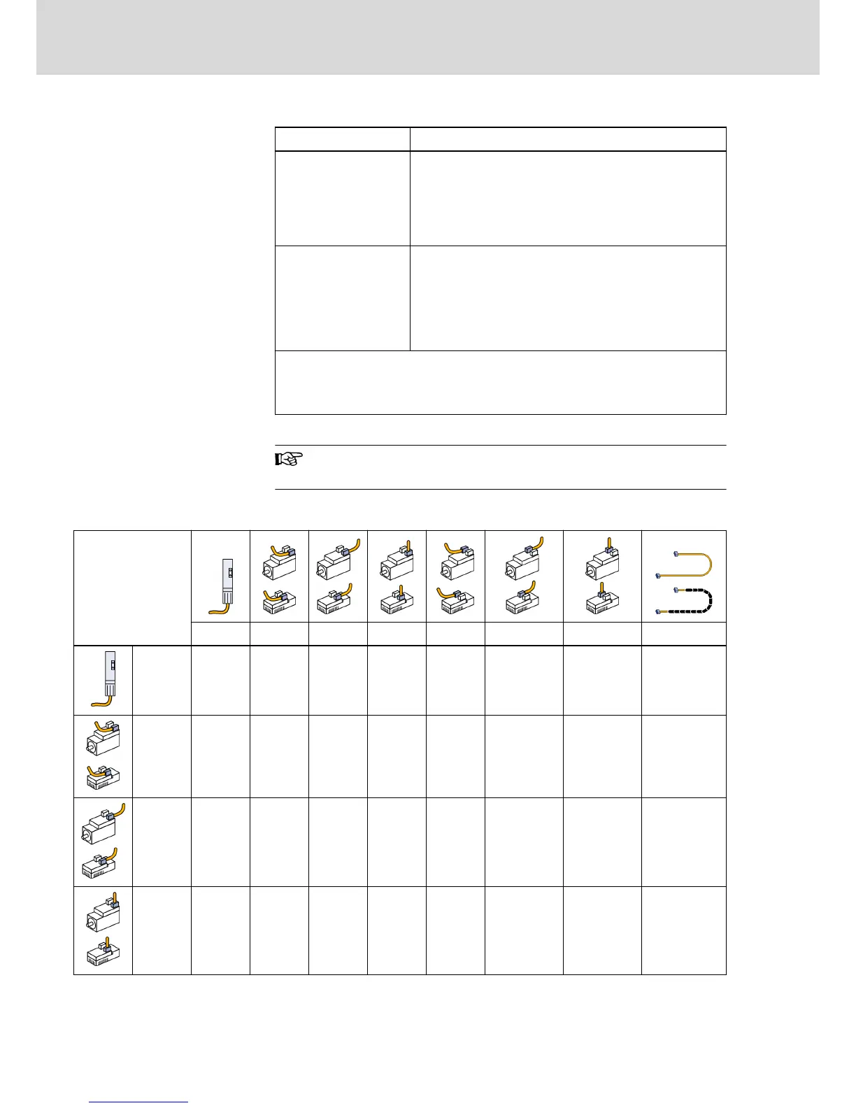
5.2.7 Selecting Hybrid Cable for Appropriate Connection
Hybrid cable RKH
(with different outgo‐
ing directions from
connection point
X3.1 or X3.2 at KSM
and KMS)
KCU X3.1 X3.1 X3.1 X3.2 X3.2 X3.2 RKH0700
KCU - - - -
RKH030
1
RKH0401 RKH0501 RKH0501
X3.1 -
RKH000
1
RKH010
0
RKH020
2
- - - RKH0202
X3.1 -
RKH010
0
RKH020
0
RKH020
4
- - - RKH0204
X3.1 -
RKH020
2
RKH020
4
RKH060
0
- - - RKH0600
Bosch Rexroth AG DOK-INDRV*-KMS01******-IT01-EN-P
Rexroth IndraDrive Mi Distributed Drive Controller KMS01
34/67
Instructions for Use