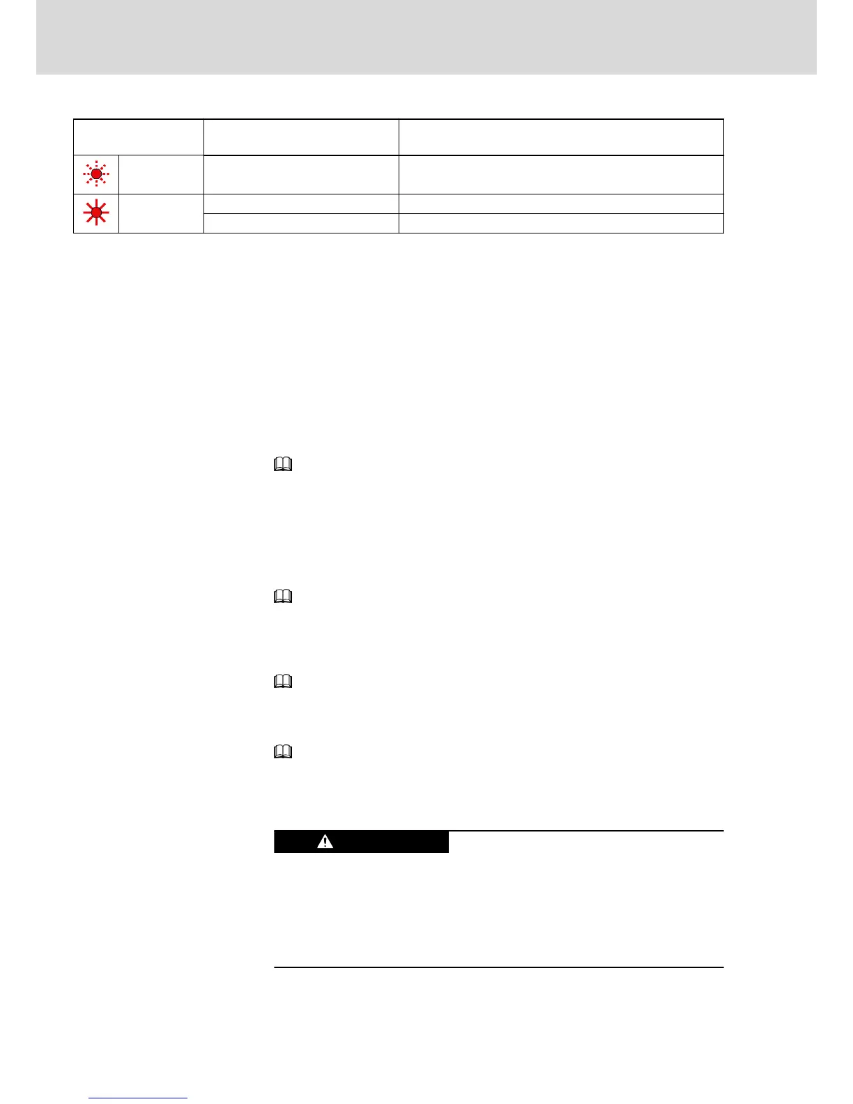
LED H14
Color / status
Significance Measures
Flashing red Errors Read exact status via "S‑0‑0095, Diagnostic message" and carry
out service function
Red Booting phase Wait until booting phase is over (approx. 2 minutes)
System error Switch off and on; replace hardware, if necessary
Fig.5-12: LED Displays KSM/KMS (up to MPB-07V10)
Firmware Functions
Easy Startup Mode
The easy startup mode is intended for initial commissioning. Easy startup can
be carried out with the commissioning software "Rexroth IndraWorks D". For
this purpose, connect KSM/KMS via the serial interface X2 to a PC (e.g. lap‐
top for commissioning).
For easy startup, the digital inputs have been preset as follows:
● I_1 (X37.4): +24 V to activate positive direction of rotation
● I_2 (X37.2): +24 V to activate negative direction of rotation
● I_3 (X38.4): +24 V to activate drive enable
See Functional Description of firmware → "Easy Startup Mode".
Analog Outputs
KSM/KMS have no analog outputs!
Oscilloscope Function
You can use the integrated oscilloscope function described in the Functional
Description of the firmware!
See Functional Description of firmware → "Oscilloscope Function".
Patch Function
KSM/KMS have a patch function which allows reading or writing controller-in‐
ternal memory cells.
See Functional Description of firmware → "Patch Function".
Monitoring Function
For extended diagnostic possibilities, KSM/KMS have a monitoring function.
See Functional Description of firmware → "Monitoring Function".
5.3.4 Service Functions / Troubleshooting
General Information
Lethal electric shock by live parts with more
than 50 V!
Before working on live parts: De-energize installation and secure power
switch against unintentional or unauthorized re-energization.
Wait at least 30 minutes after switching off the supply voltages to allow dis‐
charging.
Check whether voltage has fallen below 50 V before touching live parts!
Bosch Rexroth AG DOK-INDRV*-KMS01******-IT01-EN-P
Rexroth IndraDrive Mi Distributed Drive Controller KMS01
40/67
Instructions for Use