12
GA--A 181
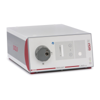
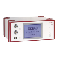
4.2.2 Ultrasound Generator and Suction Pump
Z Connect the transducer to the Ultrasound Generator.
Z Connect the suction tube of the pump to the transducer .
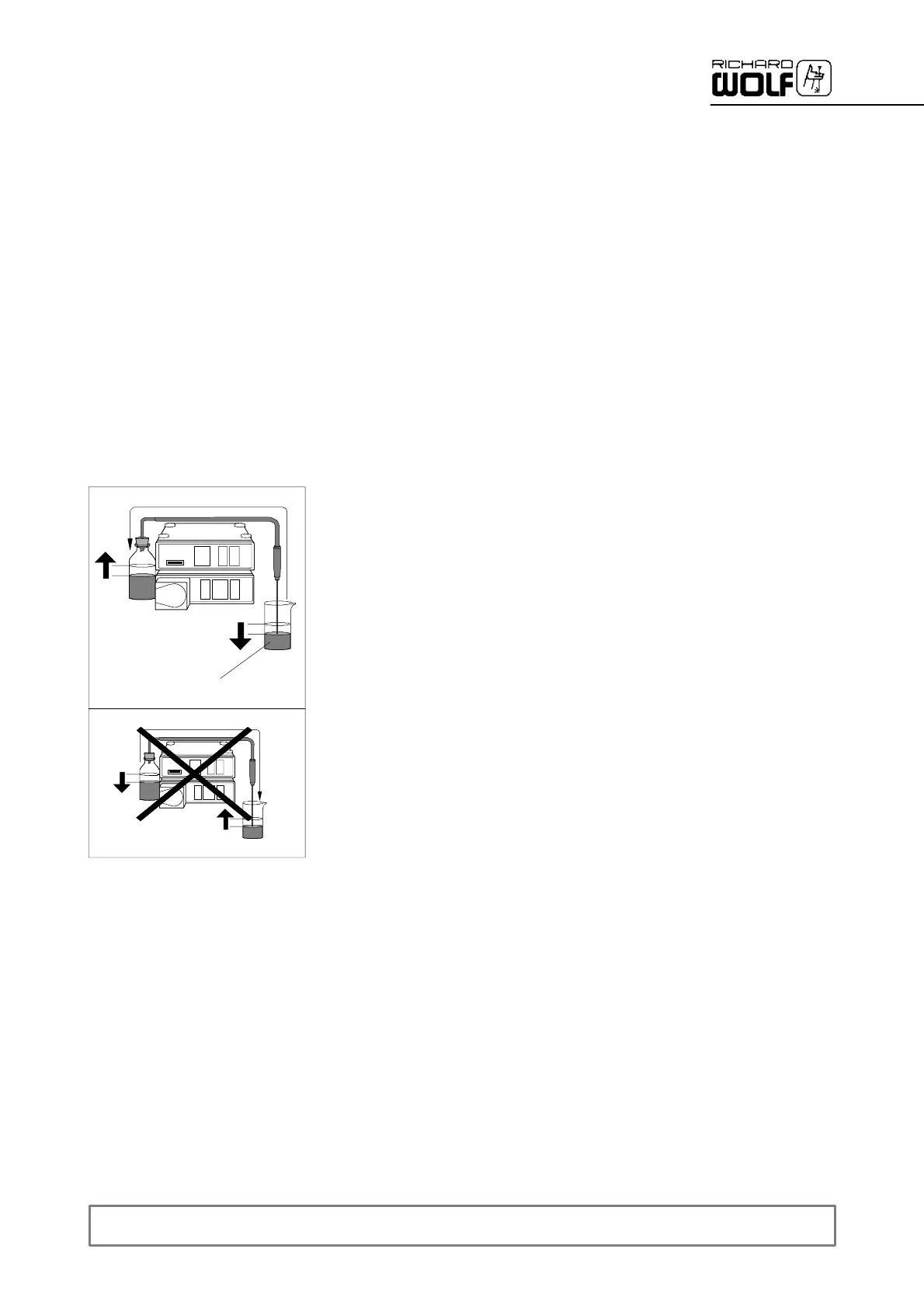
Z Place the sonotrode of a transducer in a suitable container (N) filled
with sterile liquid or irrigation fluid.
Z Switch on the Ultrasound Generator and Suction Pump.
'Pump function test: the “Transducer malfunction” warning lamp (6)
on the Suction Pump must not light up, the pump works at a low suc-
tion rate, i.e. speed.
Z Briefly actuate the foot switch.
'Pump control activation test: the suction rate/speed of the pump
must increase. If air or liquid is discharged from the sonotrode tip,
the pump tubes are incorrectly connected. Connect the tubes as
specified in the pump manual and follow the safety instructions. Re-
peat the test if required.
Z Preselect the highest power stage (4) on the Ultrasound Generator.
Z Actuate the foot switch.
'T ransducer/sonotrode function test: the sonotrode must develop au-
dible vibrations and noises. For this purpose hold the sonotrode by
the transducer and remove it from the liquid just enough for the tip to
be still immersed to ensure reliable suction. Oscillation amplitudes
must be visible along the sonotrode tube.
'Suction test. The liquid level in liquid container (N) should have
dropped visibly. If the liquid level has not decreased sufficiently,
check the sonotrode tube for clogging and clean it as described in
chapter 6 or replace it.
Z With the footswitch actuated, switch from the highest to the next lower
power stage.
'Generator malfunction monitoring test. During the switch--over the
“Generator malfunction” warning lamp (7) must light up briefly.
Z Repeat the switch--over test in all power stages including the lowest
power stage.
N