8
GAS LINE
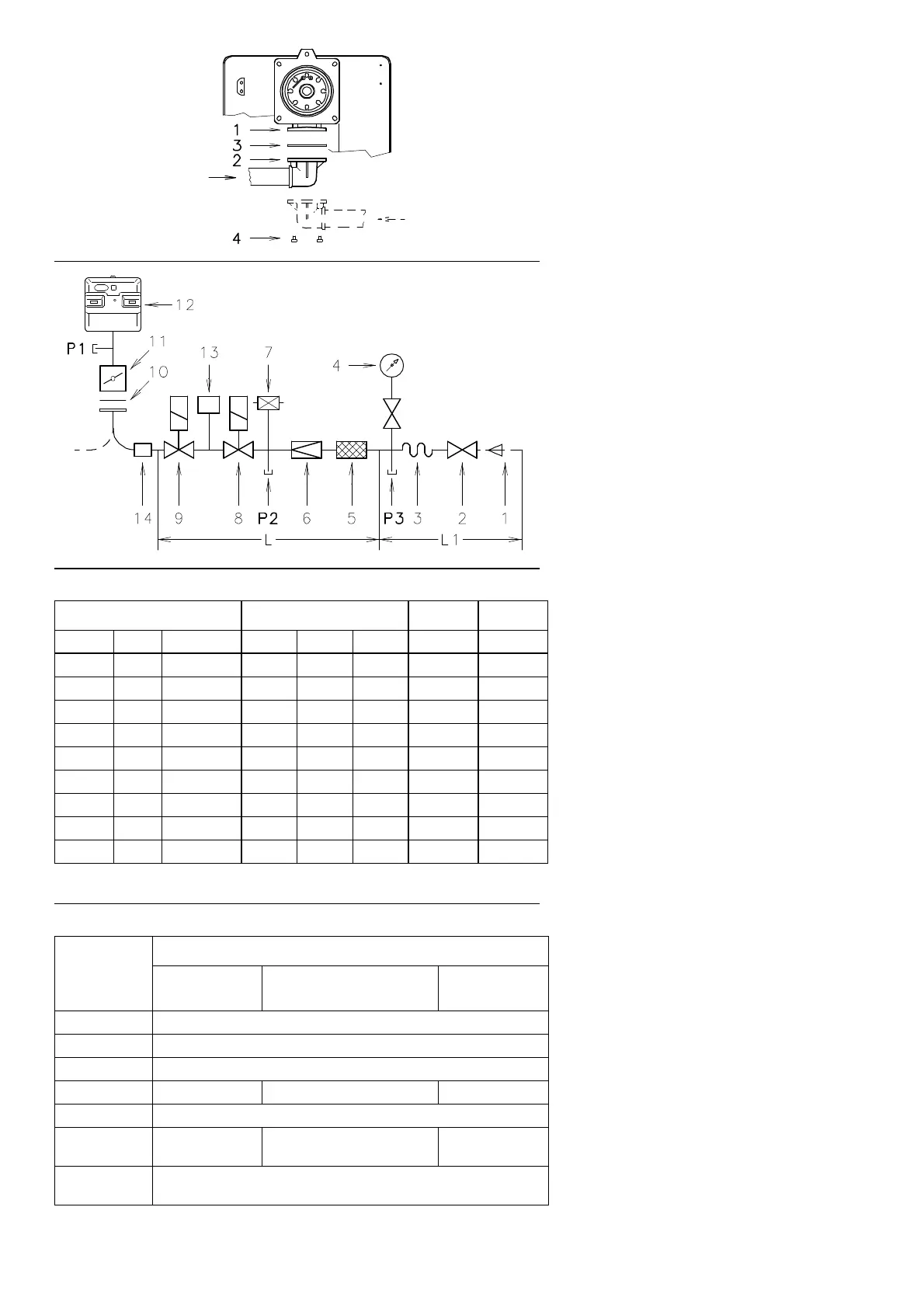
• The gas train must be connected to the gas
attachment 1)(A), using flange 2), gasket 3)
and screws 4) supplied with the burner.
• The gas train can enter the burner from the
right or left side, depending on which is the
most convenient, see fig.(A).
• Gas solenoids 8)-9)(B) must be as close as
possible to the burner to ensure gas reaches
the combustion head within the safety time
range of 3 s.
• Make sure that the pressure governor calibra-
tion range (colour of the spring) comprises the
pressure required by the burner.
GAS TRAIN (B)
It is type-approved according to EN 676 Stand-
ards and is supplied separately from the burner
with the code indicated in Table (C).
KEY (B)
1 - Gas input pipe
2 - Manual valve
3 - Vibration damping joint
4 - Pressure gauge with pushbutton cock
5 - Filter
6 - Pressure governor (vertical)
7 - Minimum gas pressure switch
8 - Safety solenoid VS (vertical)
9 - Adjustment solenoid VR (vertical)
Two adjustments:
• ignition delivery (rapid opening)
• maximum delivery (slow opening)
10 - Standard issue burner gasket with flange
11 - Gas adjustment butterfly valve
12 - Burner
13 - Gas valve 8)-9) leak detection control
device.
In accordance with EN 676 Standards, gas
valve leak detection control devices are
compulsory for burners with maximum out-
puts of more than 1200 kW.
14 - Gas train/burner adaptor.
P1 - Pressure at combustion head
P2 - Pressure down-line from the pressure gov-
ernor
P3 - Pressure up-line from the filter
L - Gas train supplied separately with the code
indicated in Table (C)
L1 - The responsibility of the installer
KEY TO TABLE (C)
C.T. =Gas valves 8) - 9) leak detection control
devices:
- = Gas train without gas valve leak detec-
tion control device; device that can be
ordered separately and assembled sub-
sequently (see Column 13).
♦= Gas train with assembled VPS valve
leak detection control device.
13 =VPS valve leak detection control device.
Supplied separately from gas train on
request.
14 =Gas train/burner adaptor.
Supplied separately from gas train on
request.
Note
See the accompanying instructions for the
adjustment of the gas train.
(A)
(B)
(C)
GAS BURNERS AND RELEVANT GAS TRAINS APPROVED ACCORDING TO EN 676
Gas train L Burner 13 14
Ø C.T. Code RS 28 RS 38 RS 50 Code Code
3/4” − 3970076 • − − 3010123 3000824
1” − 3970077 • • • 3010123 3000824
1”
1/4
− 3970144 • • • 3010123 −
1”1/2 − 3970145 • • • 3010123 −
1”1/2 − 3970180 • • • 3010123 −
2” − 3970146 − • • 3010123 3000822
2” − 3970181 − • • 3010123 3000822
2” ♦ 3970160 − • • − 3000822
2” ♦ 3970182 − • • − 3000822
GAS TRAIN COMPONENTS
Code
Components
Filter
5
Pressure governor
6
Solenoids
8 - 9
3970076 Multiblock MB DLE 407
3970077 Multiblock MB DLE 410
3970144 Multiblock MB DLE 412
3970145 GF 515/1 FRS 515 DMV DLE 512/11
3970180 Multiblock MB DLE 415
3970146
3970160
GF 520/1 FRS 520 DMV DLE 520/11
3970181
3970182
Multiblock MB DLE 420
D505
D935