9
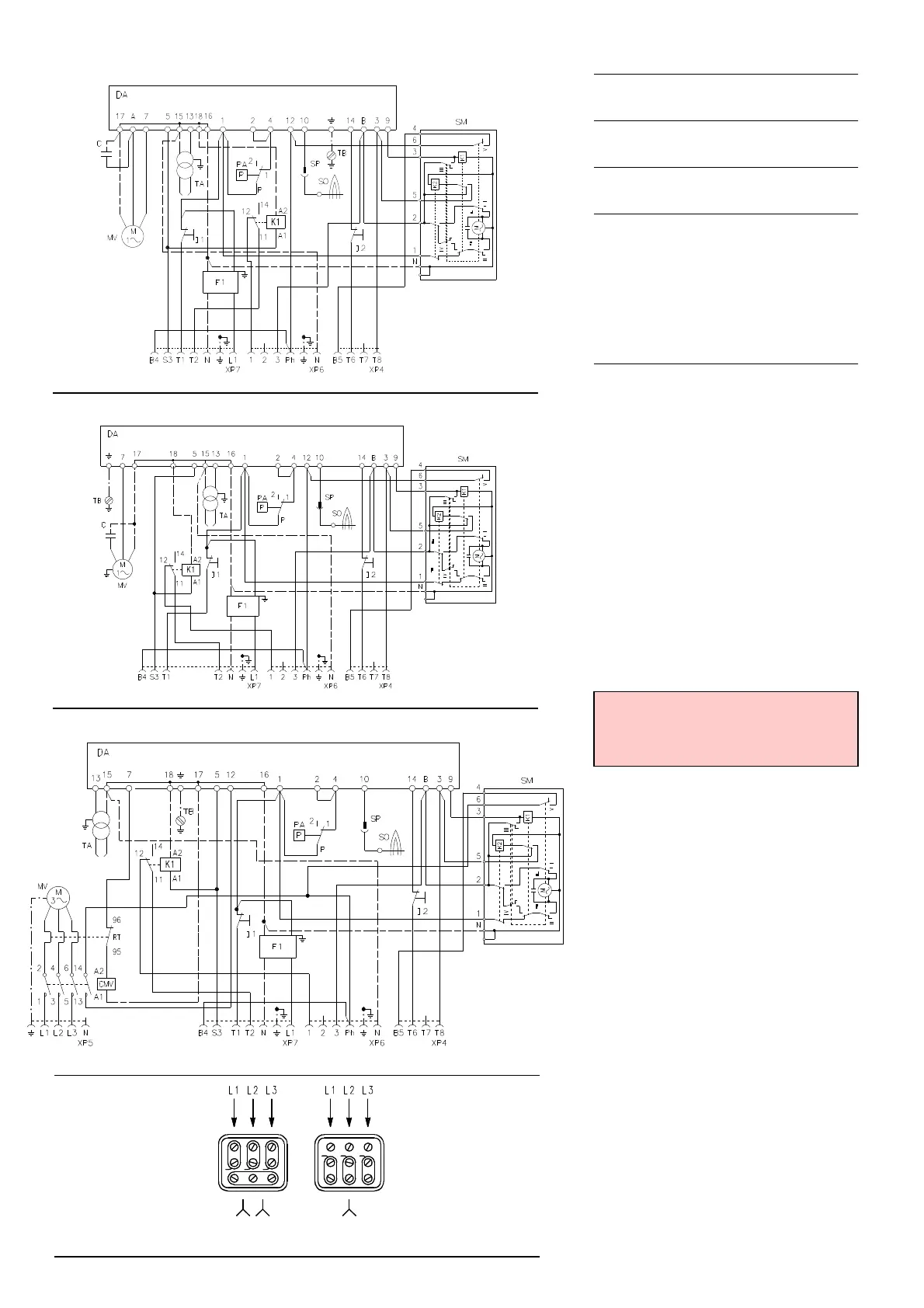
ELECTRICAL SYSTEM
ELECTRICAL SYSTEM as set up by the manu-
facturer
LAYOUT (A)
Burner RS 28 (single-phase)
LAYOUT (B)
Burner RS 38 (single-phase)
LAYOUT (C)
Burners RS 38 - 50 (three-phase)
• Models RS 38 and RS 50 leave the factory
preset for 380-460 V power supply.
• If 208-230 V power supply is used, change
the motor connection from star to double
star , see Fig. (D), and change the set-
ting of the thermal cut-out as well.
Key to Layouts (A) - (B) - (C)
C - Capacitor
CMV - Motor contactor
F1 - Protection against radio interference
DA - Control box (Landis RMG)
K1 - Relay
I1 - Switch: burner off - on
I2 - Switch: 1st - 2nd stage operation
MV - Fan motor
PA - Air pressure switch
RT - Thermal cut-out
SM - Servomotor
SO - Ionisation probe
SP - Plug-socket
TA - Ignition transformer
TB - Burner ground
XP4 - 4 pole socket
XP5 - 5 pole socket
XP6 - 6 pole socket
XP7 - 7 pole socket
ATTENTION
In the case of phase-phase feed, a bridge
must be fitted on the control box terminal strip
between terminal 6 and the earth terminal.
ELECTRICAL EQUIPMENT FACTORY-SET
RS 28 single-phase
RS 38 single-phase
RS 38 three-phase - RS 50
(D)
MOTOR CONNECTION
380V
460V
208V
230V
D3149
(A)
20082120
(B)
20082118
(C)
20082123